123
321010
1 3 42
56
7
8
9
F F I I #I #I
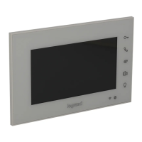
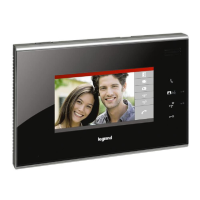
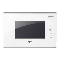
Colour 5.6” handsfree indoor handset
Configuration
Indoor handset must be configured for following parameters:
Legend
1. Serial interface connector (to download configuration)
2. Door lock device connector
3. MASTER/SLAVE selection pin
4. Configurators housing
5. RJ45 BUS connector
6. SOS alarm connector
7. Alarm sensors connector
8. Analogue small entrance panel connector
9. Anti removal sensor connector
FF : Floor number
II : Apartment number
#II : Maximum apartments quantity per floor in a riser
Two different configuration modes available for whole system:
configuration MODE 1 and configuration MODE 2. The main characteristics for each
configuration mode are listed below.
When the biggest number of #FF in whole system is ≤ 20, and the biggest number
of #II is ≤4, and the total risers number is ≤ 50, we recommend to choose (MODE 1)
configuration for system.
When the biggest number of #FF in whole system is more than 20, or the biggest
number of #II is more than 4, we suggest to use (MODE 2) configuration to setup #FF
(choose the biggest number #FF of system) and #II (choose the biggest number #II of
system), then calculate total IU number of system. If the total number (#FF * #II * R ) is
less or equal 4000, use of (MODE 2) is suggested.
POSITION MODE 1 MODE 2
F FF FF
F
I II II
I
#I
Default for #II is 04,
need not connect the configurator
II
(#II setup using same value for all
system handsets)
#I
Rear view
BT00468-b-EN 15/05/2013