ON
SD
1
2
3
4
ON
SD
1
2
3
4
CF1 CF2 CF3 CF4 CF5 CF6 CF7 CF8 C M
N N N N #F #F #I #I C M
0 0 0 5 2 5 2 8 2 0
ON
SD
1
2
3
4
ON
SD
1
2
3
4
CF1 CF2 CF3 CF4 CF5 CF6 CF7 CF8 C M
N N N N #F #F #I #I C M
0 0 0 5 2 0
GENERAL RULES FOR INSTALLATION
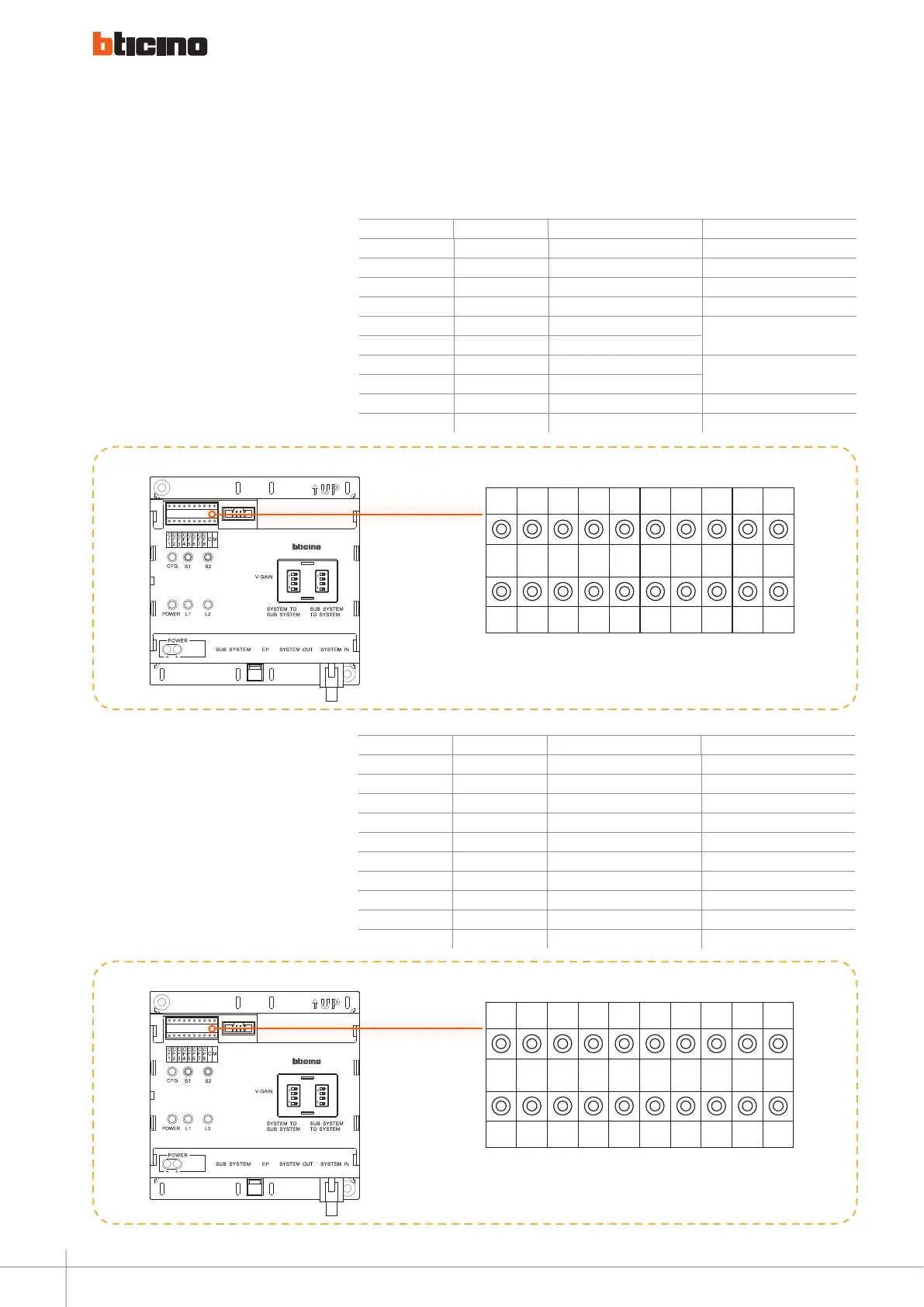
Example (A):
The number of riser shunts is 5, each
riser has 20 floors, and each floor has
4 handsets. The Switchboard that can
be called directly by this riser is no. 2.
System configuration Mode 1 is used.
The riser shunt configuration should
be as follows:
poSition Mode 1 Value for configurator reMarkS
CF1 N 0 0 no cong needed
CF2
N 0 0 no cong needed
CF3
N 0
0 no cong needed
CF4
N 5
CF5
#F
#FF is 20 (default)
No need for conguration
CF6
#F
CF7 #I #II is 4 (default)
No need for conguration
CF8 #I
C C 2
M M 0 0 no cong needed
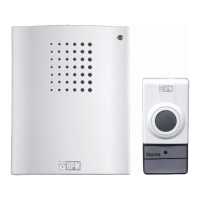
Example (B):
The number of riser shunts is 5, each
riser has 25 floors, and each floor has
8 handsets. The Switchboard that
can be called directly by this riser is
no.--># System configuration Mode 2
is used. The riser shunt configuration
should be as follows:
poSition Mode 1 Value for config. reMarkS
CF1 N 0 It is ok not to insert congurator 0
CF2
N 0 It is ok not to insert congurator 0
CF3
N 0
It is ok not to insert congurator 0
CF4
N 5
CF5
#F 2
CF6
#F 5
CF7 #I 0 It is ok not to insert congurator 0
CF8 #I 8
C C 2 It is ok not to insert congurator 0
M M 0 It is ok not to insert congurator 0
A
B
Accessory configuration examples
48