N N N CF4 CF5 CF6 CF7
N N N
FF
min
FF
min
#I #I
CF8 CF9 CF10CF11 TYP ASR M LE
FF
max
FF
max
TYP ASR M LE
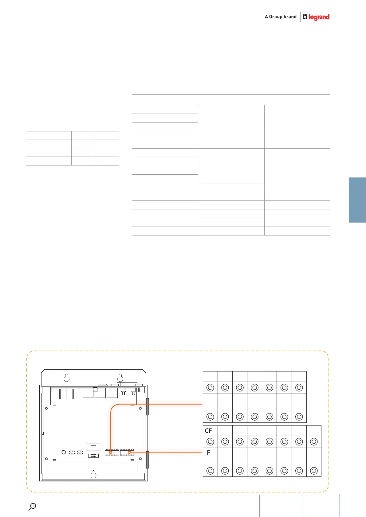
Congurators position for power supply
323005
power supply configuraTion
Possible configuration way for
power supply
Mode 1 Mode 2
Resistor conguration √ √
Keyboard conguration √ √
RS232 conguration √ √
configuration Mode 1 (1 pwS for each floor) Mode 2
N
NNN
NNN
N
N
CF4
FF Min FF Min
CF5
CF6
#II
CF7
CF8
FF Max FF Max
CF9
CF10
CF11
Type Type Type
ASR ASR ASR
M M
M
LE
LE LE
meaning of each
configuraTor socKeT pin
NNN: Power supply address (range
1–256), only when TYP= 1, the power
supply address will be valid. It means
when TYP= 0, there is no need to
configure NNN.
FF Min: the floor number where this
power management starts from.
FF Max: the floor number where this
power management ends. FF Max
must over or equal to FF Min.
#II: number of apartments on each
floor (at Mode 1, the default number
is 4, no need to set).
#Min handset: the address of the
first address managed by this
power supply).
#Max handset: the last handset
address managed by this
Power supply).
TYP: configuration position for the
power supply function. Used to
enable or disable the power supply
management function and the smart
power function.
ASR: set how much current the
power supply will offer to each
handset for the alarm function.
M: position to choose configuration
Mode. connecting configurator 0
means choosing Mode 1 or Mode 2.
LE: configuration position for smart
power supply management. Only
valid when TYP=1. When TYP= 0, no
need to configure that position.
49
GUIDED45 SyStEm
WWW.LEGRAND.COM