N N N CF4 CF5 CF6 CF7
N N N
FF
min
FF
min
#I #I
0 1 2 0 1 0 5
CF8 CF9 CF10CF11 TYP ASR M LE
FF
max
FF
max
TYP ASR M LE
0 2 1 0 0 0
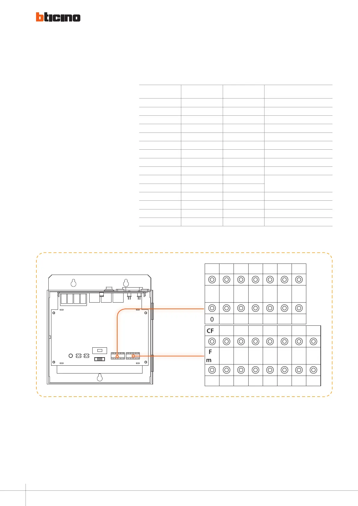
GENERAL RULES FOR INSTALLATION
Example (B):
This riser has 20 floors, and each floor
has 5 handsets. This power supply
manages 1-2 floors.
If necessary enable the smart power
function and the power management
function, the power supply address
is 12, max current of the alarm sensor
is 300 mA. System configuration
Mode 2 is used. The power supply
configuration should be as follows:
poSition Mode 1
Value for
configurator
reMarkS
CF1 N 0
CF2 N 1
CF3 N 2
CF4 FF Min 0
CF5 FF Min 1
CF6 #II 0
CF7 #II 5
CF8 FF Max 0
CF9 FF Max 2
CF10 CF10
Here conguration is not necessary for
Mode 1 and Mode 2
CF11 CF11
CF12 Type 1
CF13 ASR 0
CF14 M 0
CF15 LE 0
B
Accessory configuration examples
52