recommended pws soluTion and relaTed configuraTion
Note:
(X:) It means no configurator is needed and the configuration position is 0; others need a configurator with corresponding value.
(√:) It means configuration is needed. For the configuration procedure refer to the system configuration chapter.
CF1~CF15 is the configuring position for 323005. For the detailed meaning and configuration method please check the system configuration chapter.
no. inStallation
StatuS of SySteM
power
Supply
Solution
configuration when power Supply iS SySteM power Supply
(impedance switch of Power supply must be ON)
configuration of power Supply & apower Supply
when Power supply is assistant power supply
(impedance switch of Power supply must be OFF)
alarm Small EP
CF1
~
CF3
(NNN)
CF4
~
CF11
CF12
(Type)
CF13
(ASR)
CF14
(M)
CF15
(LE)
CF1
~
CF3
(NNN)
CF4
~
CF11
CF12
(Type)
CF13
(ASR)
CF14
(M)
CF15
(LE)
1 none none 1 X X X X X X
Under these four condition, using auxiliary power supply no
need congurate
2 none none 1 X X X X X X
3 have none 1 X X X X X X
4 have none 1 NNN X 1 0.2~9 1 X
5 none have 2 NNN √ 1 1 0/1 X X √ 2 1 0/1 X
6 none have 2 NNN √ 1 1 0/1 X X √ 2 1 0/1 X
7 have have 2 NNN √ 1 0.2~9 0/1 X X √ 2 0.2~9 0/1 X
8 have have 2 NNN √ 1 0.2~9 0/1 X X √ 2 0.2~9 0/1 X
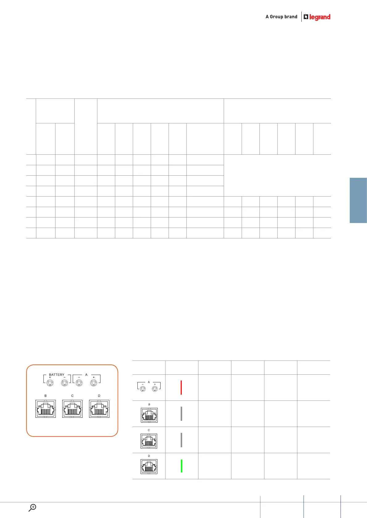
connecTion and seTup
procedure for 323005
Difference for each connector
line
colour
power
connection
Video
connection
audio
connection
data
connection
√
√ √ √ √
√ √ √ √
√ √ √
Connector for 323005
(Set 323005 as system power supply)
59
GUIDED45 SyStEm
WWW.LEGRAND.COM