8
No: IS-0685 – Rev. 2
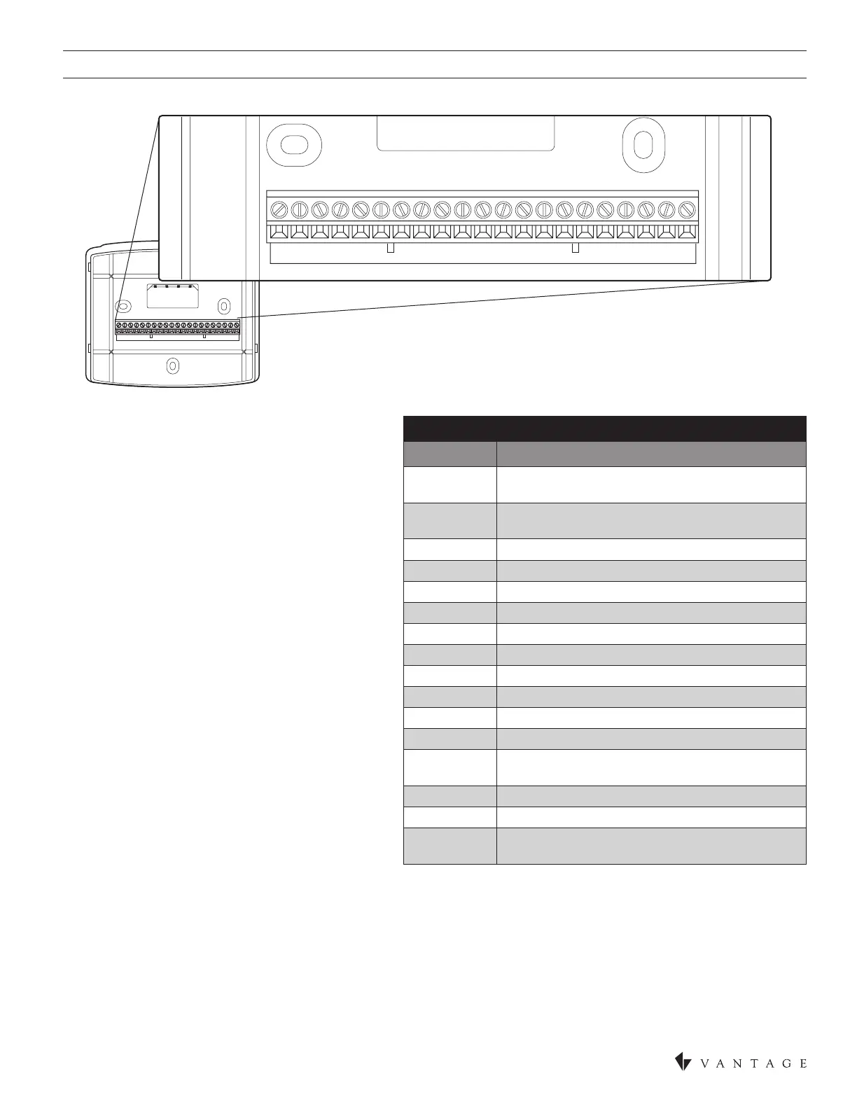
THERMOSTAT WIRING TERMINAL KEY
TERMINAL DESCRIPTION
B+ / B- Receive communication terminal
(reference CC-LINT and CC-RLINT)
A+ / A- Transmit communication terminal
(reference CC-LINT and CC-RLINT)
C 24VAC common from HVAC or external 24VAC
B Reversing valve for heat
2
O Reversing valve for cool
2
Y 1st stage cooling / compressor or dehumidier
3
Y2 2nd stage cooling / compressor
G Fan
RC 24VAC supply cooling
4
RH 24VAC supply heating
4
W2 2nd stage heat / auxiliary / E-Heat
W 1t stage heat / auxiliary / E-Heat / humidier
3
R 24VAC Thermostat power (hot) from HVAC or
external 24VAC
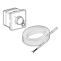
S2 and S1 Outdoor temperature sensor (optional)
T1 and T2 Remote temperature sensor (optional)
RSB and
RSA
CC-TEMPSUP or CC-HUMIDSUP
Support Module communication (half duplex)
5
THERMOSTAT TERMINAL WIRING DIAGRAM
WIRE SPECIFICATIONS
• 18-24 gauge thermostat wire
• CAT-5 or equivalent for communication terminals
• Vantage Station Bus – see page 9
INSTALLATION NOTES
• Ensure power at the thermostat location isoff.
• Loosen screw terminals, insert stripped wire and re-
tighten. See Wiring to CCWLINT CC-RLINT For HVAC
or Humidity Control in SECTION TWO.
• Push the excess wire back into the opening and plug
the wall opening to prevent drafts.
NOTE 1: If the Vantage thermostat is replacing an old
thermostat, check whether the old thermostat is powered
from an external 24VAC transformer or through the
RC or RH terminals. If thermostat power is provided
by an external 24VAC source do not jumper from the
R terminal to either the RC or the RH terminal. The
C* terminal should have connections from the HVAC
equipment, an external 24VAC transformer (if it exists)
and the CC-WLINT or the CC-RLINT interface station.
NOTE 2: Older systems may not have a C (common)
wire. If a common wire is not available from the HVAC
equipment please see the auxiliary switch solution from
Vantage, part number STAT-AUXS. This part adapts
existing 3 or 4 wire systems to 4 or 5 wire systems
requiring a common connection. Detailed instructions
are included with the STAT-AUXS.
1
Refer to Vantage Integration later in this instruction and Vantage CC-WLINT / CCRLINT Installation instructions.
2
O and B terminals are both de-energized when system mode is OFF or in AUTO when the heating and cooling equipment is idle.
3
When the unit is congured for humidistat mode.
4
Jumper between RC & RH is used in single transformer systems (see wiring diagrams).
5
See Support Modules referenced earlier in this instruction or refer to the Support Module’sliterature for wiring details – shipped with
each support module.
B+ A+ B- A- CBOYY2 GRCRHW2W RS2S1T1T2RSB RSA
B+ A+ B- A- CBOYY2 GRCRHW2W RS2S1T1T2RSB RSA