CS10/CS15 & GS Sensors, Operation
38
Viva Uno rover
setup
7. Insert the SD card and the battery into the CS field controller.
8. Attach the GS GNSS antenna cap to CS field controller. Refer to the
CS10/CS15 User Manual.
9. Connect the antenna cable to the external GNSS antenna and to the GS
GNSS antenna cap.
When you are using the external GNSS antenna, ensure that you
selected the correct Rover antenna (AS05 Tripod GHM).
10. To hang the instrument on the tripod leg, use the hand strap on the rear of
the CS field controller.
11. Attach the tribrach bracket to the carrier and insert the instrument height
meter into the tribrach bracket.
12. Measure the antenna height using the instrument height meter.
13. Press the ON/OFF button on the CS field controller for at least 2s to switch
on the CS field controller.
Step Description
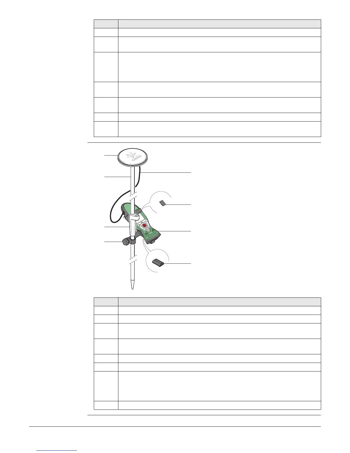
a) GNSS antenna AS05
b) Pole
c) Grip for pole
d) GHT62 holder
e) 1.2 m antenna cable
f) SD card
g) Viva Uno instrument (CS field controller
with GS GNSS cap)
h) GEB211/GEB212 battery
Step Description
1. Attach the GHT62 holder to the pole.
2. Insert the SD card and the battery into the CS field controller.
3. Attach the GS GNSS antenna cap to CS field controller. Refer to the
CS10/CS15 User Manual.
4. Clip the CS field controller into the holder and lock it by pushing the locking
pin into the locked position.
5. Screw the GNSS antenna to the top of the pole.
6. Adjust the height of the telescopic rod to suit.
7. Connect the antenna cable to the external GNSS antenna and to the GS
GNSS antenna cap.
When you are using the external GNSS antenna, ensure that you
selected the correct Rover antenna (AS05 Tripod GHM).
8. Press ON/OFF button on the CS field controller to switch on.
0012601_001
a
c
d
b
e
f
h
g