Unity Motorhome
70
Electrical System Operation
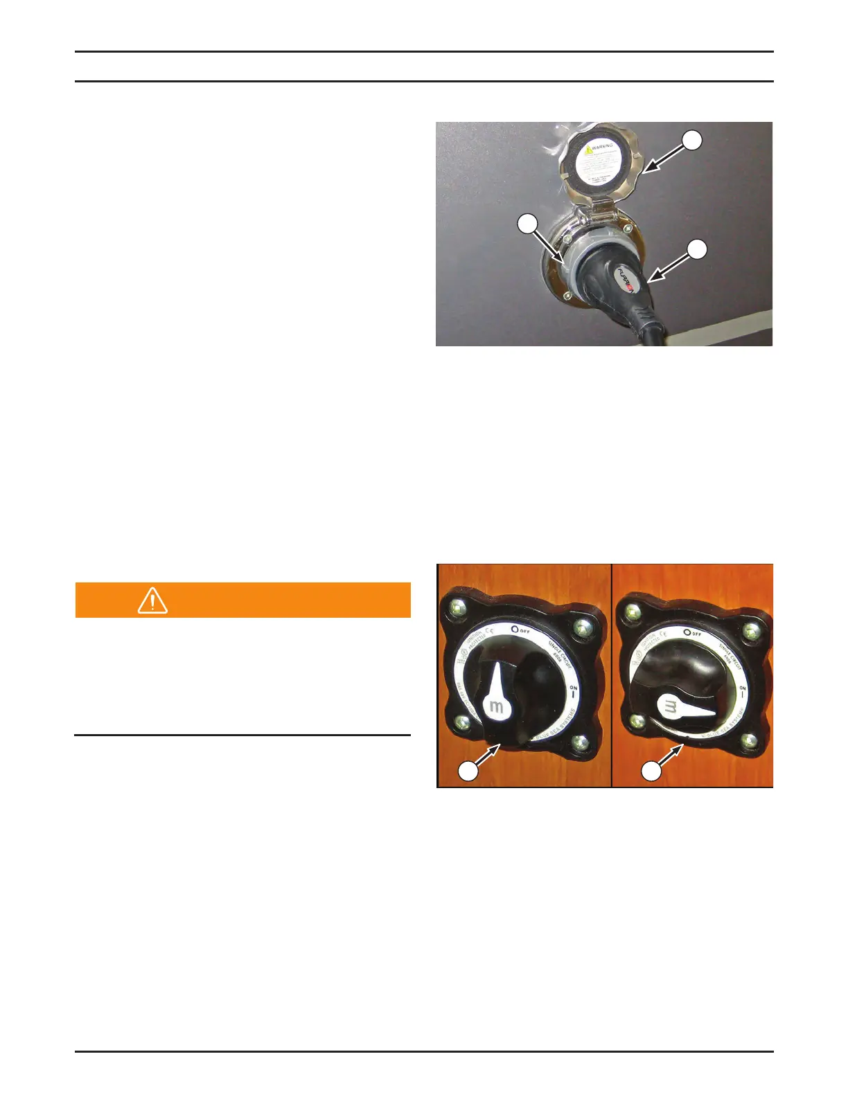
Battery Disconnect Switch
The 12 volt DC electrical supply is controlled
by the battery disconnect switch located in
the coach doorway. The switch minimizes
amperage draws on the coach batteries when
the motorhome is not in use or in short-term
storage. Rotate the switch to the 12 o’clock
position (4) to disconnect the batteries. Rotate
to 3 o’clock position (5) to connect the battery.
3
1
2
Electrical System Operation
Electrical Supply
Your motorhome is equipped with two electrical
systems that operate on separate voltages: an
internal 12 volt DC system (coach batteries),
and an external 120 volt AC system (shore
power).
The 12 volt DC System draws power from
either the engine’s battery and charging system
while driving or from the coach batteries when
parked.
The 12 volt DC System operates from the
coach batteries, from shore power through the
inverter/charger, or from the generator through
the inverter/charger. The coach batteries charge
automatically when the unit is connected to
shore power or when the engine or generator
is running.
The 120 volt AC System operates either from
the optional 120 volt AC generator installed
in your motorhome or from the outside shore
power connection.
Do not connect the external power cord
until you have conrmed the campground
has the proper polarity and grounding.
Improper grounding or reverse polarity may
cause component failure, injury, or death.
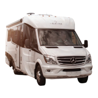
Shore Power
To operate using shore power, connect the 120
volt AC power supply cable (stored in the driver’s
side rear exterior storage compartment) to the
external receptacle located on the driver’s side
of the coach.
To connect the 30 amp power supply cable,
rotate the cover (1) counterclockwise and lift
up. Insert the power cable (2) into the socket
by aligning the locking tab on the connector
pin with the slot in the socket. Turn the socket
clockwise to lock in place. Use a locking ring (3)
to prevent accidental disconnection.
4 5
Warning