Unity Motorhome
66
Appliance & Equipment Operation
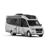
Battery Disconnect Switch
The 12 volt C electrical supply is controlled
y the attery disconnect switch located in
the coach doorway The switch eliinates
aperage draws on the coach atteries when
the otorhoe is in storage Rotate the switch
to the 12 oclock position to disconnect the
atteries Rotate to 3 oclock position 5 to
connect the attery
3
1
2
Electrical System Operation
Electrical Supply
our otorhoe is euipped with two electrical
systes that operate on separate voltages an
internal 12 volt C syste coach atteries,
and an eternal 120 volt C syste shore
power
The 12 volt C Syste draws power ro
either the engines attery and charging syste
while driving or ro the coach atteries when
parked
The 12 volt C Syste operates ro the
coach atteries, ro shore power through the
invertercharger, or ro the generator through
the invertercharger The coach atteries charge
autoatically when the unit is connected to
shore power or when the engine or generator
is running
The 120 volt C Syste operates either ro
the optional 120 volt C generator installed
in your otorhoe or ro the outside shore
power connection
Do not connect the external power cord
until ou have conrmed the campground
has the proper polarity and grounding.
Improper grounding or reverse polarity may
cause component failure, injury, or death.
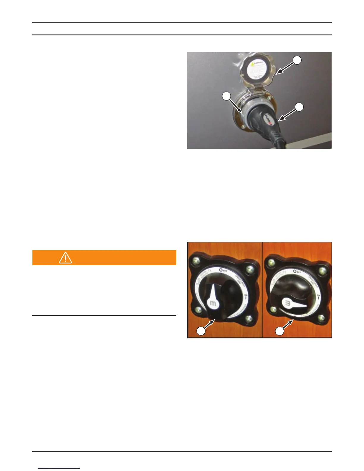
Shore Power
To operate using shore power, connect the 120
volt C power supply cale stored in the drivers
side rear eterior storage copartent to the
eternal receptacle located on the drivers side
o the coach
To connect the 30 ap power supply cale,
rotate the cover 1 counterclockwise and lit
up nsert the power cale 2 into the socket
y aligning the locking ta on the connector
pin with the slot in the socket Turn the socket
clockwise to lock in place se a locking ring 3
to prevent accidental disconnection
4 5
Warning