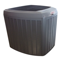
Do you have a question about the Lennox XP19-024 and is the answer not in the manual?
Details nominal tonnage, connections, and refrigerant charge for XP19 units.
Provides line voltage, overcurrent protection, and circuit ampacity for XP19 models.
Lists optional accessories available for the XP19 series units.
Ensures proper system matching for warranty and operation, referencing Engineering Handbook.
Procedure for removing and reinstalling the main access panel.
Detailed steps for safely removing and installing louvered panels.
Illustrates the layout of major components in the XP19 unit.
Explains the design and operation of the two-stage scroll compressor.
Details how a scroll compressor compresses gas through orbiting scrolls.
Describes how bypass ports and a slider ring enable two-stage operation.
Procedure to verify compressor capacity stages using a thermostat and gauges.
Verifies 24VDC signal from LSOM to the compressor solenoid plug.
Checks the internal unloader solenoid resistance for proper operation.
Details bad/good solenoid checks and the function of the contactor.
Explains low/high pressure switches and compressor capacitor.
Describes the operation and internal workings of the variable speed fan motor.
Guidelines for applying line voltage and capacitor discharge safety.
Details normal motor rocking, soft-start, and shutdown features.
Steps to diagnose issues with the variable speed condenser fan motor.
Instructions for replacing the condenser fan motor.
Describes the filter drier's role in removing moisture and foreign matter.
Procedures for checking system dryness, acid, and foreign matter.
Explains the purpose of the accumulator in trapping liquid refrigerant.
Describes the LSOM module, its LEDs, and troubleshooting indications.
Explains connections for thermostat (Y2, L) and DC solenoid.
Procedures for verifying LSOM installation and resetting alert codes.
Details codes for Power, System Check, and Abnormal Conditions.
Explains fault and lockout codes for pressure, temperature, and electrical issues.
Details the defrost control board, its components, and diagnostic LEDs.
Explains pressure switch connections and the 5-strike lockout feature.
Describes the ambient, coil, and discharge sensors and their resistance values.
Provides resistance values for ambient, coil, and discharge sensors at various temperatures.
Illustrates the physical placement of ambient, coil, and discharge sensors.
Explains how ambient, coil, and discharge sensors detect faults and potential lockouts.
Details how defrost cycles are initiated, controlled, and terminated.
Procedure for initiating and performing defrost test cycles.
Explains how to interpret diagnostic LEDs for fault conditions.
Details how to activate test mode and its impact on unit operation.
Provides a flowchart for understanding defrost board test mode operations.
Diagram illustrating the sequence of events for board calibration.
Details how defrost cycles are initiated based on frost or time.
Explains LED states and their corresponding causes and solutions.
Details specific fault and lockout codes for pressure and sensor issues.
Describes the crankcase heater and its controlling thermostat.
Details refrigerant line sets and gauge manifold connections for charging.
Instructions for accessing Schrader ports and torque specifications for components.
Details the operation and front-seating of liquid and vapor line service valves.
Guidelines for adjusting R410A refrigerant charge based on line set length.
Steps for leak testing the system using nitrogen and R410A.
Procedure for evacuating the system to remove noncondensables and moisture.
Method for weighing in refrigerant charge, especially in cool weather.
Procedure for charging the unit using the subcooling method.
Provides normal operating pressures for heating and cooling stages.
Method to verify unit charge by comparing ambient and liquid line temperatures.
Guidelines for system service, recovery, and preventing moisture ingress.
Lists essential maintenance checks for the outdoor unit at the start of each season.
Schematic showing electrical connections for the XP19 heat pump outdoor unit.
Labels key components and their terminal connections on the wiring diagram.
Details first and second stage cooling operation, including capacity modulation.
Explains low and high capacity heating stages based on ambient temperature.
Describes how the system operates during a defrost cycle.





 Loading...