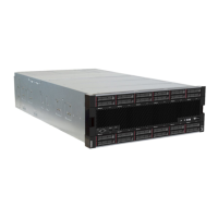
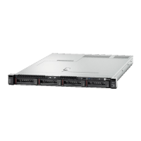
Front view of server
Figure 4 “Front view of the server (front cover installed)” on page 25 illustrates the front view of the server,
with the front cover installed, identifying the drive bays.
Figure 4. Front view of the server (front cover installed)
Figure 5 “Front view of the server (front cover removed)” on page 25 illustrates the front view of the server.
Figure 5. Front view of the server (front cover removed)
Table 26. Components on the front of the server
Callout Callout
1 2.5-inch-drive bays (12-23) (on some models)
7 Power button and power LED
2 Fan slots (1-12) 8 Front operator panel with pull-out LCD display
3 2.5-inch-drive bays (0-11) 9 USB 2.0 port
4 System-error LED 10 USB 2.0 Lenovo XClarity Controller management port
5 System ID button/LED 11 VGA Video port
6 Network activity LED
1 2.5-inch-drive bays (12-23) (on some models)
The drive bays are used to install 2.5-inch drives. When you install drives, follow the order of the drive bay
numbers. The EMI integrity and cooling of the server are protected by having all drive bays occupied. The
vacant drive bays must be occupied by drive bay fillers or drive fillers.
2 Fan slots (1-12)
Chapter 2. Server components 25
 Loading...


