86 Information SET-01
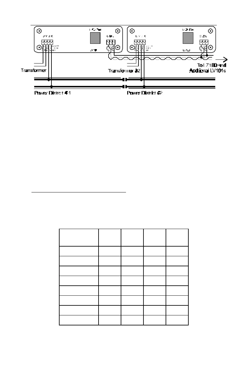
Connecting 2 LV101s to the layout
The command signals reach additional LV101s through terminals C
and D of the first one. Each LV101 must be connected to its own
transformer. The number of transformer/Power Station combinations
needed for the layout thus depends on the power needs of your
layout.
The power blocks of several LV101 must necessarily have the same
polarity. Terminal J of one and terminal J of the next LV101 must
therefore be connected to the same rail. Otherwise there will be a
short when passing a dividing gap. (See Figure 1)
17.5.5 Setting the track voltage
If desired you can set the level of the DCC track voltage. This setting
is handy if, for example, you desire a lower starting voltage in the
area of gauge N. You can choose an range between 11.5V and 22V.
DCC Track
Voltage
SW 1 SW 2 SW 3 SW 4
11.5 Volts On On On N/A
13 Volts Off On On N/A
14.5 Volts On Off On N/A
16 Volts Off Off On N/A
17.5 Volts On On Off N/A
19 Volts Off On Off N/A
20.5 Volts On Off Off N/A
22 Volts Off Off Off N/A