Wiring according to EMC
Always observe these basic rules
12
l
EDBEMV82EV EN 3.0
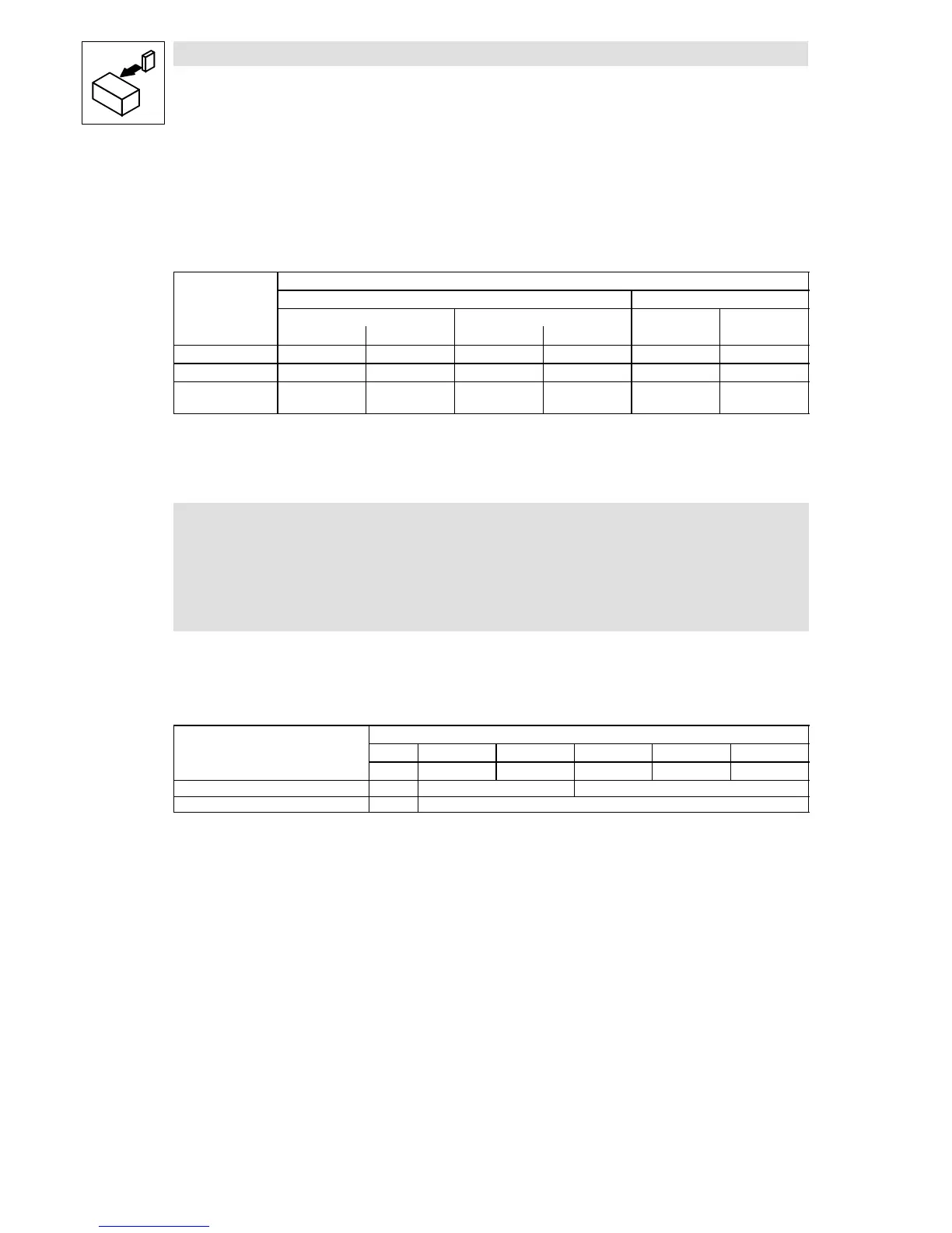
3.1.6 Wiring on the motor side
Measures for suppressing the interfering radiation depend on the length and design of the motor
cable. The following table provides an overview of the required RFI measures:
Radio interference suppression
Motor cable length
shielded unshielded
1)
up to 50 m 50 ... 100 m
2)
up to 100 m 100 ... 200 m
2)
Continuous shield Interrupted shield Continuous shield Interrupted shield
RFI filter 9 9 9 9 9 9
Motor filter — — 9 9 — 9
Motor interference
suppression module
— (9) — (9) (9) (9)
9 Measure is required
(9) Check measure in case of EMC interferences
1)
Interfering radiation is not considered
2)
Operation is only permissible with a switching frequency of 8 kHz, U/f characteristic control, maximum output frequency 480 Hz
Note!
The motor cable is highly susceptible to interferences. Hence the following applies:
The motor cable must not contain any further cables (e.g. for brake control,
separate fans etc.).
One exception is the temperature monitoring cable of the motor.
Comply with the specification of the motor cable
z
Use shielded low-capacitance motor cables only:
Requirements on the motor cable capacitance
Cable cross-section
mm
2
1 1.5 2.5 4 6
Capacitance per unit length AWG 18 16 12 10 10
Core/core [pF/m] <75 < 100
Core/shield [pF/m] < 150
z
The motor must be designed for a rated voltage of > 500 V AC (test voltage 2 kV AC).
z
The maximum permissible motor cable length amounts to 50 m without external measures
(e.g. motor filter)
Connect the shield of the motor cable correctly
Always connect the motor cable shield to both sides - controller and motor.
z
Shield connection to the controller/control cabinet
– Connect the shield with a large surface to the EMC shield sheet using a shield clamp.
– For this purpose use the enclosed shield clamp.
– Continue the shield after the shield clamp to the terminals of the inverter or the clamping
point. Do not exceed an unshielded cable length of 40 mm.
– In addition, it is recommended to connect the shield to PE (see in Fig. 2).
z
Shield connection at the motor
– Connect the shield at the motor terminal box with EMC cable glands.