Preface and general information
2
l
EDBEMV82EV EN 3.0
1 Preface
Based on the brochure ”EMC basic information” this second part ”Wiring according to EMC
requirements” informs the user of the 8200 vector series about the application of the basic devices
and accessories according to EMC requirements.
The Lenze accessories for 8200 vector series comprises many components which are relevant with
regard to EMC.
The following components are included in the accessories:
z
Mains chokes
z
RFI filters
z
Motor interference modules
z
Motor filters
The assignment and mode of operation of these EMC components are described in detail.
1.1 About these Instructions
z
These Instructions are intended for all persons who design and install the 8200 vector frequency
inverters.
z
These Instructions describe the structure of a CE-typical drive system with the 8200 vector
frequency inverter. If you follow the instructions you can assume that
– the 8200 vector frequency inverters comply with the standards ”Electromagnetic
compatibility (EMC)”.
– the operation with 8200 vector frequency inverters will be free of any EMC interferences.
1.2 Terminology used
Term In the following text used for
Controller Any Lenze frequency inverter, Lenze servo inverter or Lenze DC controller
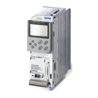
vector 8200 vector frequency inverter
Drive Lenze controller in combination with a geared motor, a three-phase AC motor or other Lenze drive components.
AIF Automation InterFace: Interface for a communication module.
FIF Function InterFace: Interface for a function module.
Cxxxx/y Subcode y of code Cxxxx (e. g. C0410/3 = subcode 3 of code C0410)
Xk/y Terminal y on terminal strip Xk (e. g. X3/28 = terminal 28 on terminal strip X3)
E xx-yyy Cross reference to a page

 Loading...


