Braking operation
11−4
L
EDB82MV752 EN 5.2
Connection to E82MV551_4B, E82MV751_4B, E82MV152_4B, E82MV152_4B
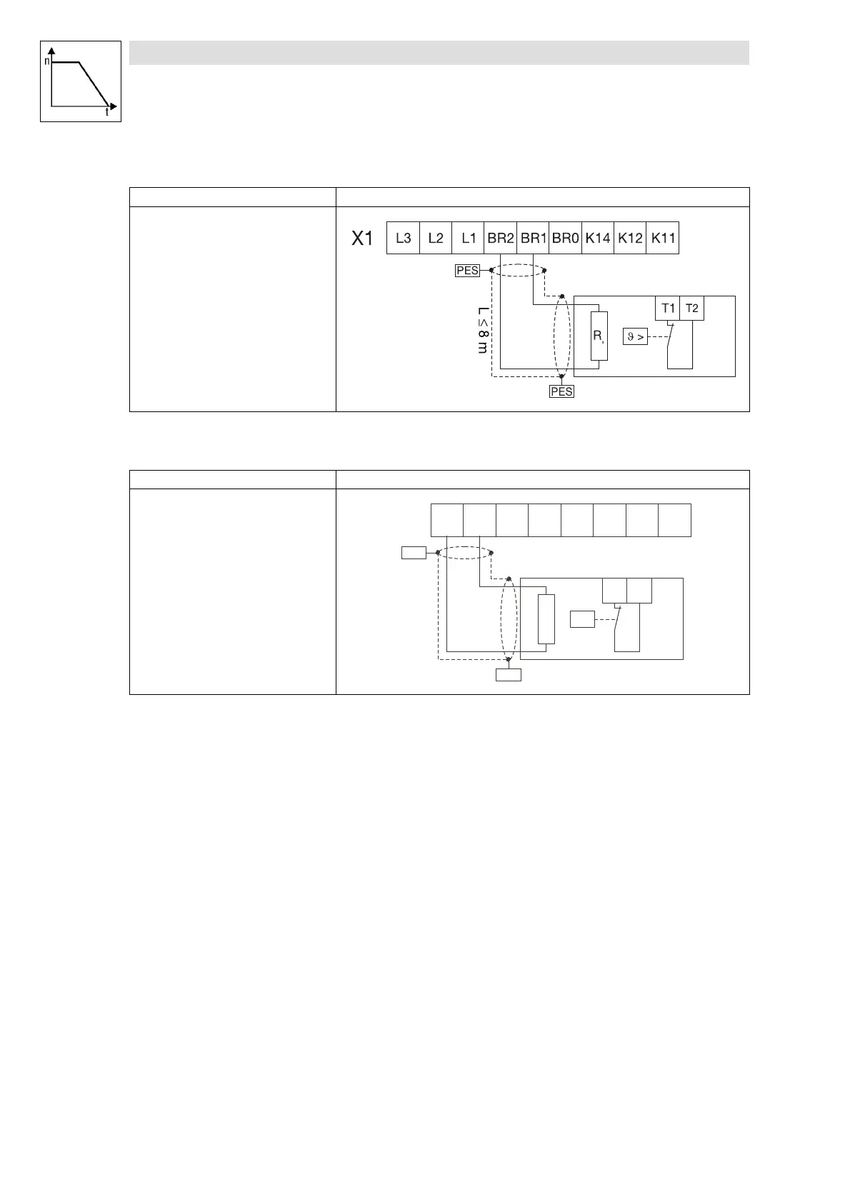
Procedure Connection diagram
The brake resistor R
B
is connected to the
terminal strip X1 of the motec.
1. Open the motec.
2. Mount the cable connector for the cable
gland.
3. Unscrew the terminal strip X1 and remove
it from its support.
4. Remove the bridge between BR1 and BR0.
5. Connect the brake resistor to BR2 and
BR1.
6. Reconnect the terminal strip X1.
If the external resistor is disconnected,
BR1 and BRO must be bridged again.
Otherwise, the motec can be destroyed.
Connection to E82MV302_4B, E82MV402_4B, E82MV552_4B, E82MV752_4B
Procedure Connection diagram
The brake resistor R
B
is connected to the
terminal strip X2 of the motec.
1. Open the motec.
2. Mount the cable connector for the cable
gland.
3. Connect the brake resistor to BR2 and
BR1.
T1
T2
BR1
BR2
U
V W PE2 T1 T2
X2
R
B
ϑ >
PES
PES
L ≤ 8m
 Loading...
