Installation
Electrical installation − Connections
4−16
L
EDB82MV752 EN 5.2
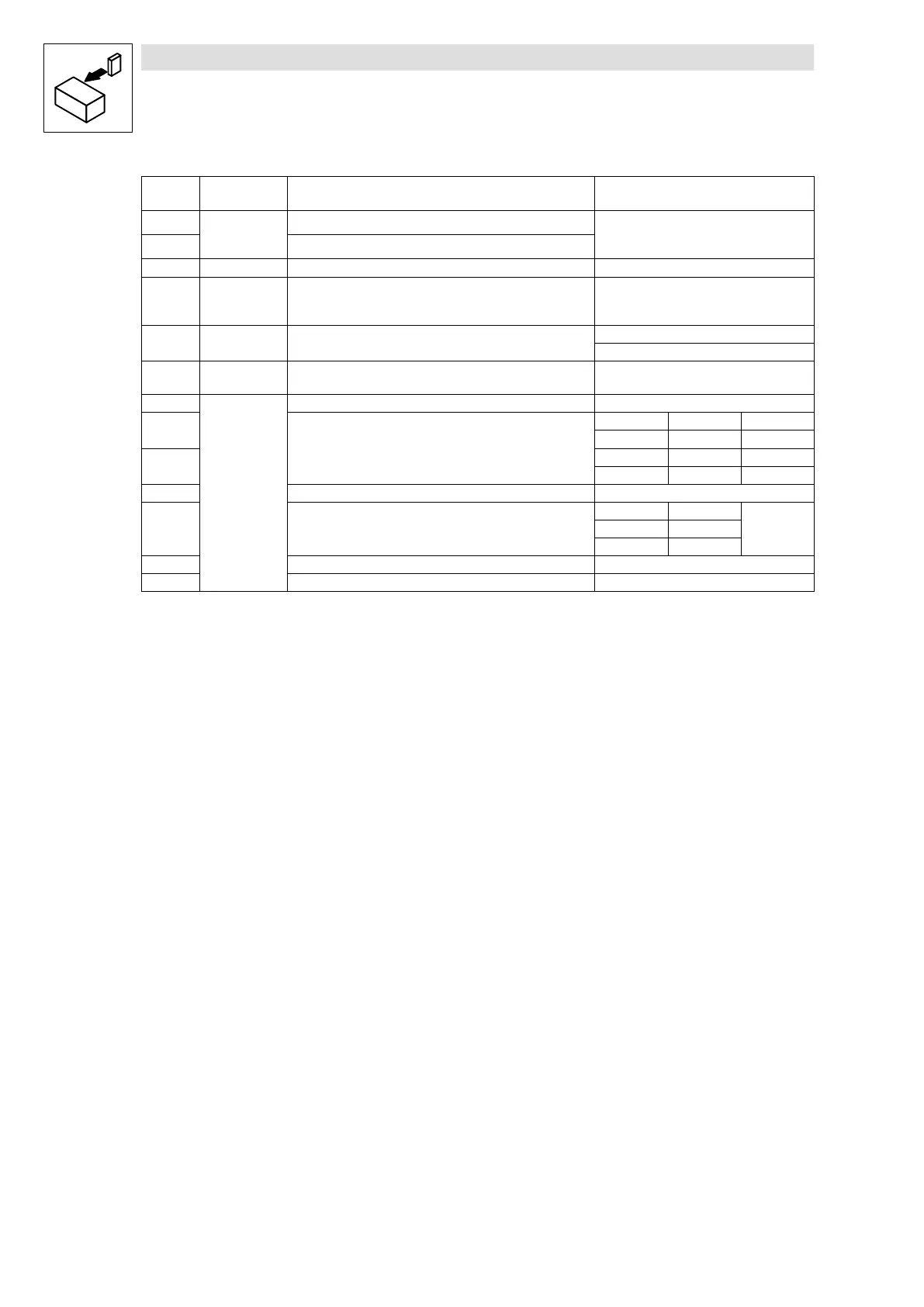
X3.3/ −6− Signal type Function Level
(Lenze setting, in bold print)
A1
Digital outputs
Ready for operation
0/+20 V at DC internal
0/+24 V at DC external
A2 not prefabricated
7 − GND, reference potential −
A4 Frequency
output
DC bus voltage HIGH:
+18 V...+24 V (HTL)
LOW: 0 V
59 − DC supply for X3/A1 and X3/A2
+20 V (internal, bridge to X3/20)
+24 V (external)
20 − Internal DC voltage supply for control of digital inputs and output +20 V 10 %
28
Digital inputs
Controller inhibit (CINH) 1 = START
E1
2)
Activation of JOG frequencies
JOG1 = 20 Hz
JOG2 = 30 Hz
JOG3 = 40 Hz
E1 E2
JOG1 1 0
E2
2)
JOG2 0 1
JOG3 1 1
E3 DC−injection brake (DCB) 1 = DCB
E4 Change of direction of rotation
CW/CCW rotation
E4
CW 0
CCW 1
E5 not prefabricated −
E6 not prefabricated −
2)
Optional frequency input 0 ... 102.4 kHz, single−tracked or double−tracked, configuration via C0425
4.2.4.4 Wiring of bus function modules
System bus (CAN): see CAN Communication Manual
For all other bus function modules (e.g. PROFIBUS−DP, INTERBUS, ...) see the accompanying
Mounting Instructions or Communication Manual.