Installation
Electrical installation − Connections
4−14
L
EDB82MV752 EN 5.2
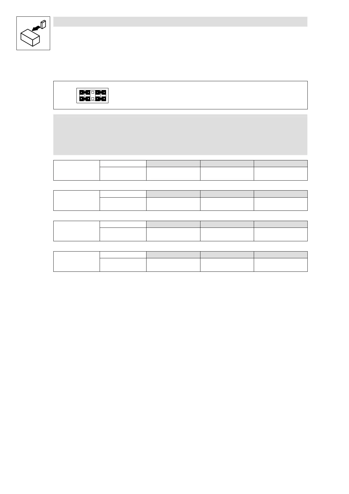
Jumper setting for inputs
10
9
8
7
2
1
4
3
6
5
Lenze setting (see bold print in tables)
1 − 3
2 − 4
7 − 9
8 − 10
) Note!
If a setpoint potentiometer is internally supplied via X3.2/9, the jumper must be set
to a voltage range between 0 ... 5 V. Otherwise not the whole speed range can be
covered.
X3.1/1U
Analog input1, AIN1
Possible levels
0 ... 5 V 0 ... 10 V
2)
−10 V ... +10 V
Jumper 7 − 9: free 7 − 9 7 − 9
Code C0034/1 = 0 C0034/1 = 0 C0034/1 = 1
X3.1/2U
Analog input2, AIN2
Possible levels
0 ... 5 V 0 ... 10 V
2)
−10 V ... +10 V
Jumper 8 − 10: free 8 − 10 8 − 10
Code C0034/2 = 0 C0034/2 = 0 C0034/2 = 1
X3.1/1I
Analog input1, AIN1
Possible levels
0 ... 20 mA 4 ... 20 mA 4 ... 20 mA
1)
Jumper any any any
Code C0034/1 = 2 C0034/1 = 3 C0034/1 = 4
X3.1/2I
Analog input2, AIN2
Possible levels
0 ... 20 mA 4 ... 20 mA 4 ... 20 mA
1)
Jumper any any any
Code C0034/2 = 2 C0034/2 = 3 C0034/2 = 4
1)
open−circuit monitored
2)
Lenze setting (delivery status)
 Loading...
