EasyManua.ls Logo

Lenze E82ZAFIC001 User Manual

Lenze E82ZAFIC001
71 pages
To Next Page IconTo Next Page
Page #1 background imageLoading...
Page #1 background image
EDS82ZAFIC
.IDp
Ä.IDpä
Communication Manual
INTERBUS
l
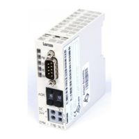
E82ZAFIC001 / E82ZAFIC010
Function module
L−force Communication

Table of Contents

Questions and Answers:

Lenze E82ZAFIC001 Specifications

General IconGeneral
BrandLenze
ModelE82ZAFIC001
CategoryI/O Systems
LanguageEnglish

Summary

About this documentation

Document history

Details document revisions and dates.

Conventions used

Explains symbols, formatting, and terminology.

Terminology used

Defines key terms used in the manual.

Notes used

Explains pictographs and signal words for warnings.

Safety instructions

General safety information

Basic safety measures for Lenze components.

Device- and application-specific safety instructions

Specific safety rules for the module and its use.

Residual hazards

Hazards related to electrical shock and ESD.

Product description

Application as directed

Specifies intended use and incompatible uses.

Identification

Explains how to identify the module and its versions.

Connections and interfaces

Describes LEDs, DIP switches, and connectors (A-G).

Technical data

General data

Basic specifications.

Connection terminals

Terminal assignments and functions.

Communication time

Cycle and processing times.

Installation

Mechanical installation

Mounting instructions for the function module.

Electrical installation procedures

Covers wiring, supply, terminals, cables, and connectors.

Commissioning

Pre-Commissioning Checks

Essential checks before initial power-up.

Commissioning Steps and Configuration

Step-by-step setup, host config, data length, voltage.

Process data transfer

Lenze device control

Using Lenze device control for data transfer.

Process data signals for 8200 vector / 8200 motec

Configuring process output and input data signals.

DRIVECOM Control Features

State machine, control/status words, and bits.

Parameter data transfer

Configure PCP Communication

Setup and access for Parameter Data Channel (PCP).

Initialise PCP Communication and Services

CRL entries and available PCP services.

Diagnostics

LED status displays

Explains the meaning of the LED indicators on the module.

Troubleshooting and fault elimination

Lists common faults, causes, and remedies.

Code table

Communication-relevant Lenze codes

Codes related to communication configuration.

Monitoring

Codes for monitoring functions.

Diagnostics

Codes related to diagnostics.

Important controller codes

Details key controller codes, like parameter set management.

Related product manuals