Installation
4-16
L
MA9300PLC EN 1.4
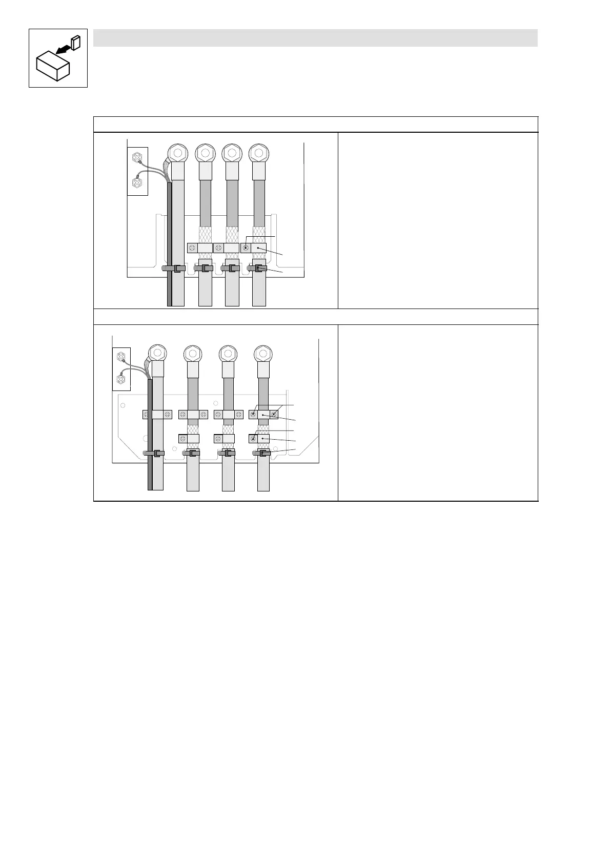
Types 9330 and 9331
T1
T2
PE
UV
W
M5 X 12
• Carry out strain relief using cable binders Q.
• Correct shield connection with shielded cables:
– Apply motor cable shield to shielding plate using clip and
M5x12 bolts
R.
– Fix the shield of the thermal contact (see
^ 4-28 ) at
the PE stud next to the motor connection with a surface
as large as possible.
Type 9332
T1
T2
PE
U
V
W
M5 X 12
M4 X 12
• Carry out strain relief using clamps and M4x12 bolts S.
– An additional strain relief/fixing is possible with cable
binders
Q.
• Correct shield connection with shielded cables:
– Apply motor cable shield to the shielding plate using clip
and M5x12 bolts
R.
– Fix the shield of the thermal contact (see
^ 4-28 ) at
the PE stud next to the motor connection with a surface
as large as possible.
Fig. 4-8 Proposal for the motor connection

 Loading...


