Installation
4-23
L MA9300PLC EN 1.4
Connection of digital signals
Digital signals are connected via the 2 x 7-pole terminal block X5.
The levels of the digital inputs and outputs are PLC compatible.
Only use relays with low-current contacts for switching signal cables
(recommendation: relays with gold-plated contacts).
Connection for external voltage supply
A 3
2 8
A 1
A 2
5 9
_
3 9
2 2 k
1 0 R
G N D 2
+
Q S P
J O G
R D Y
| n s e t | < n x
M m a x
3 k
3 k
3 k
3 k
3 k
3 k
3 k
5 0 m A
5 0 m A
5 0 m A
5 0 m A
A 4
X 5
+
_
=
=
2 4 V
2 4 V
9 3 X X
G N D 2
R F R
R
E 1 E 2 E 3 E 4 E 5
L
P r o c e s s o r
b o a r d
T R I P -
S e t / R e s e t
T R I P
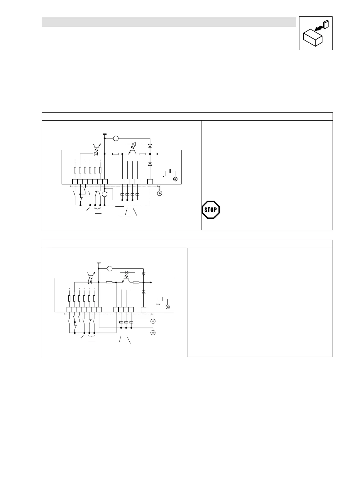
The external voltage source supplies the digital inputs and outputs.
• If the external supply voltage is also to be used as an alternative
supply for the control electronics (backup operation in case of mains
failure):
– For this, make the connection illustrated as a broken line.
– The external voltage source must be able to drive a current > 1 A.
This ensures that all actual values are still detected and processed, even
after mains disconnection.
• Connection of the external voltage source:
– Supply voltage at X5/59
– External mass at X5/39
9300PLC119
A 3
2 8
A 1
A 2
5 9
_
3 9
2 2 k
1 0 R
G N D 2
+
Q S P
J O G
R D Y
| n s e t | < n x
M m a x
3 k
3 k
3 k
3 k
3 k
3 k
3 k
5 0 m A
5 0 m A
5 0 m A
5 0 m A
A 4
X 5
+
_
=
=
2 4 V
2 4 V
9 3 X X
G N D 2
R F R
R
E 1 E 2 E 3 E 4 E 5
L
P r o c e s s o r
b o a r d
T R I P -
S e t / R e s e t
T R I P
The maximum permitted voltage difference between GND2
(terminal X5/39) and the PE of the controller is 50 V.
Connection for internal voltage supply
9300PLC121
A 3
2 8
E 1 E 2 E 3 E 4 E 5
A 1
A 2
5 9
3 9
2 2 k
1 0 R
R
L
G N D 2
Q S P
R D Y
| n s e t | < n x
F I X E D 1
3 k
3 k
3 k
3 k
3 k
3 k
3 k
A 4
R F R
X 5
5 0 m A
5 0 m A
5 0 m A
5 0 m A
+
_
2 4 V
=
J O G
9 3 X X
M m a x
G N D 2
P r o c e s s o r
b o a r d
T R I P -
S e t / R e s e t
Configuration of the internal voltage supply
• Set a freely assignable digital output (DIGOUTx) to HIGH level.
– For instance, terminal X5/A1: The variable “DIGOUT_bOut1_4 (%QX1.0.0)”
must be set to HIGH (TRUE) using DDS. After having started the PLC
program, a 24 V DC voltage is available at the output X5/A1.

 Loading...


