Installation and commissioning
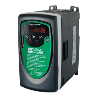
DIGIDRIVE
Variable speed drive
38
Réf. 3218 GB - 4.33 / d - 02.02
LEROY-SOMER
3.6.2 - Power circuit diagram - 3-phase mains supply
QS : Fused isolator
AU : Emergency stop button
SB1 : Power off button
SB2 : Power on button
KM1 : Line contactor
FR : Thermal relay of optional braking resistors
* : See section 7.3
• To enable the braking resistor, set parameter 30 = 0 (for the
parameter-setting procedure, see section 4.3).
UVW
L2 L3
M
3 ~
AU
SB1
FR
(RF)
SB2 KM1
Fu1
Remote control
power supply
KM1
Mains supply
L1
QS
KM1
+DC
RF
Braking
resistor
option *
FR
RFI filter
option
DIGIDRIVE
PE
or
•
or DBR
 Loading...