Installation and commissioning
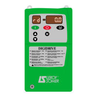
DIGIDRIVE
Variable speed drive
40
Réf. 3218 GB - 4.33 / d - 02.02
LEROY-SOMER
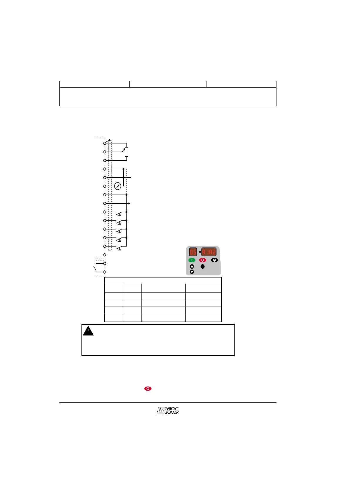
3.6.4 - Control circuit diagrams
3.6.4.1 - Control via terminal block using factory setting - Analogue reference 1 (A1), or
2 (A2), and jog operation
M
1
0V
RP
Reference A1
(analogue voltage input)
+10V
0V (negative logic)
Reference A2
(analogue current input)
Analogue output (motor frequency)
+24V (positive logic)
Logic output (zero frequency)
Unlock
Run forward/Stop
Run reverse/Stop
A1/A2 reference selection
Jog
(see 15 in section 4.8)
Fault relay
2
3
4
5
6
7
PL1
PL2
8
9
10
11
12
13
14
15
16
• The original configuration of the drive assumes positive logic
operation.
• Using a drive with a control system which has a different control logic
may cause unwanted starting of the motor.
• See section 4.4 for configuring the drive for negative logic, and connect
the common to 0V.
Term. 12 Term. 13 Reference Assoc. parameter
0 0 Reference A1 -
1 0 Reference A2 16 (*)
0 1 Jog 15
1 1 Jog 15
05 = A1.A2
RP:10 kΩ potentiometer (2 kΩ minimum)
(*) : CAUTION :
If 16 is set to 4-20mA or 20-4 mA (with detection of signal break), and the value of
reference A2 is < 3mA, the drive switches to "CL". It is then impossible to
select reference A1. Simply set 16 = 4-.20 or 20.-4 (without break detection), then
clear the fault by pressing , before selecting reference A1.
 Loading...