Installation and commissioning
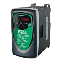
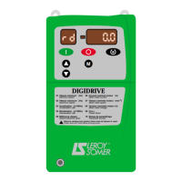
DIGIDRIVE
Variable speed drive
Réf. 3218 GB - 4.33 / d - 02.02
LEROY-SOMER
61
4
4
6
6
Fieldbus transmission speed
R - W
0 to 9 0
4
4
7
7
Fieldbus diagnostics
R - W
± 9999 0
4
4
8
8
Control mode
R - W
0 to 3 3 then 1
4
4
9
9
Boost
R - W
0 to 25.0% of motor 3.0% motor
Un Un
5
5
0
0
Assignment of terminal 13 to
R - W
On, OFF OFF
PTC sensors
Parameter Name Type Adjustment range
Factory
4.8.2 - Explanation of parameters 1
1
1
1
to
5
5
0
0
:Preset frequency 1
Adjustment range : ±1000.0 Hz
Factory setting : 0
Used to define preset frequency FP1.
For negative frequencies, see parameter
1
1
7
7
.
:Preset frequency 2
Adjustment range : ±1000.0 Hz
Factory setting : 0
Used to define preset frequency FP2.
For negative frequencies, see parameter
1
1
7
7
.
:Preset frequency 3
Adjustment range : ±1000.0 Hz
Factory setting : 0
Used to define preset frequency FP3.
For negative frequencies, see parameter
1
1
7
7
.
: Preset frequency 4
Adjustment range : ±1000.0 Hz
Factory setting : 0
Used to define preset frequency FP4.
For negative frequencies, see parameter
1
1
7
7
.
:Jog operation frequency
Adjustment range : 0 to 400.0 Hz
Factory setting : 1.5 Hz
Used to define the operating frequency of
the jog operation input.
To enable jog operation, close terminal 13
"Jogging" and give a Run forward
command via terminal 10 or Run reverse
command via terminal 11.
(See the diagram in section 3.6.4.1).
:Selection of the type of
signal on analogue input 2
(A2)
Adjustment range : 0-20, 20-0, 4-20, 20-4,
4-.20, 20-.4
Factory setting : 4-.20
Used to define the type of signal on the
analogue current input:
0-20: 0-20 mA.
20-0: 20-0 mA.
4-20: 4-20 mA (with detection of signal
break ≤ 3 mA).
20-4: 20-4 mA (with detection of signal
break ≤ 3 mA).
4-.20 : 4-20 mA (without detection of
signal break).
20-.4: 20-.4 mA (without detection of signal
break).
1
1
1
1
1
1
2
2
1
1
3
3
1
1
4
4
1
1
5
5
1
1
6
6
 Loading...