Leuze electronic GmbH + Co. KG BPS 37 3
Figure 2.1: Laser apertures, laser warning and information signs........................................................ 7
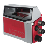
Figure 3.1: Device construction of the BPS 37 ..................................................................................... 8
Figure 3.2: Connection BPS "Stand alone" .......................................................................................... 9
Figure 3.3: BPS connection with MA 4.7 connection unit ..................................................................... 9
Figure 3.4: BPS connection with MS 37 103 modular connector hood .............................................. 10
Table 4.1: General specifications ...................................................................................................... 11
Figure 4.1: BPS 37 dimensioned drawing .......................................................................................... 12
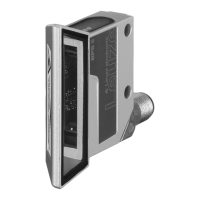
Figure 4.2: MS 37 103 dimensioned drawing ..................................................................................... 13
Figure 4.3: BPS 37 reading field curve ............................................................................................... 13
Table 5.1: Accessories/order codes .................................................................................................. 14
Figure 5.1: MA 4.7/MA 4D.7 connection unit / dimensioned drawing................................................. 15
Figure 5.2: BT 56 mounting device..................................................................................................... 16
Figure 6.1: Mounting example BPS 37 ............................................................................................... 18
Figure 6.2: Beam exit on the BPS 37 ................................................................................................. 19
Figure 6.3: Application example ......................................................................................................... 19
Figure 6.4: BPS 37 sub-D pin assignments........................................................................................ 20
Table 6.1: Connection description BPS 37........................................................................................ 21
Figure 6.5: Connection with MA.......................................................................................................... 21
Figure 6.6: Connection directly with BPS ........................................................................................... 21
Figure 6.7: Connection diagram for switching input and switching output of the BPS 37................... 22
Figure 6.8: Pin assignment of the BPS 37 with MS 37 103 ................................................................ 23
Figure 6.9: Pin assignment - PWR IN................................................................................................. 24
Figure 6.10: Pin assignment - HOST/BUS IN.......................................................................................24
Figure 6.11: Pin assignment - SERVICE.............................................................................................. 25
Table 6.2: Cable lengths and shielding ............................................................................................. 25
Figure 7.1: Connecting the service interface to a PC or terminal ....................................................... 27
Figure 9.1: Installation window ........................................................................................................... 29
Figure 9.2: Installation directory.......................................................................................................... 29