Leuze electronic Commissioning steps at a glance
Leuze electronic BPS 8 9
TNT 35/7-24V
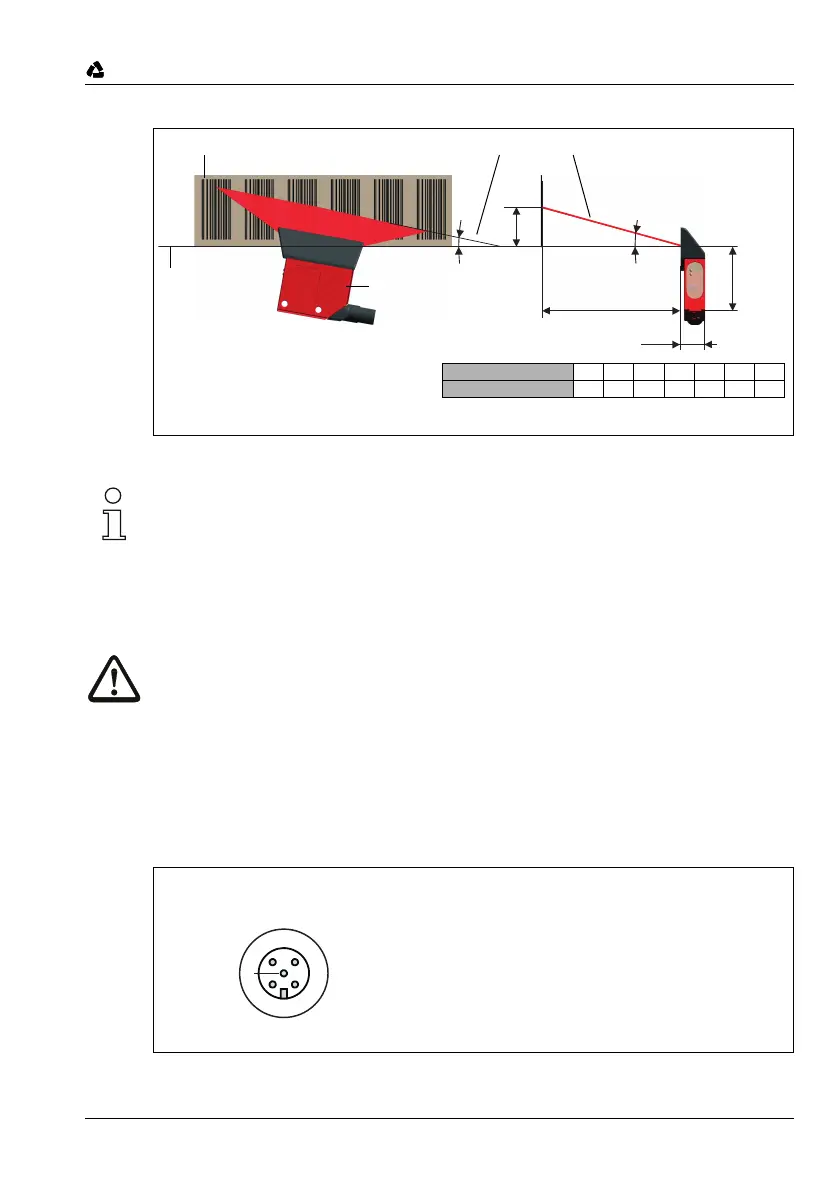
Figure 3.2: Beam exit and device arrangement for the BPS 8 SM 100
Notice!
When mounting, consider the angle of inclination
α
of
10° for a barcode tape height of 47mm,
5° for a barcode tape height of 30mm, or 25mm
in the vertical direction, and the working range of the reading field curve.
➔ chapter 7.1 on page 36
Attention!
For the position calculation, the scanning beam of the BPS 8 must be incident on the bar-
code tape without interruption. Ensure that the scanning beam is always incident on the bar-
code tape when the system is moving.
Connecting voltage supply and interface
Connecting the voltage supply/RS 232 directly at the BPS 8
The voltage supply and the RS 232 interface are connected via the M12 connection PWR IN
at the BPS 8.
Figure 3.3: BPS 8 - assignment M12 connector PWR IN
15˚
α
17,4
51
X
Read distance
Reference plane
Barcode tape
BPS 8 SM 100
Pitch of scanning beam
Pitch of scanning beam:
α = 10° for a tape height of 47mm
α = 5° for a tape height of 30mm or 25mm
Read distance 60 70 80 90 100 110 120
Height X 16 19 21 24 27 29 32
➁
3
21
4
5
RXD GND
VIN
SWIN/SWOUT
TXD
PWR IN
Plug
(A-coded)
 Loading...