User Manual for BPS-i30
www.levitronix.com
PL-4042-00, Rev05, DCO# 21-057
450 Ohm shunt input, no galvanic isolation.
The designation of the analog inputs can be
changed with Levitronix
®
Service Software.
0..10 V = 0..x rpm (Speed Mode)
LPP-30.1: x = 16000 rpm
LPP-30.3: x = 20000 rpm
LPP-30.6: x = 16000 rpm
LPP-30.1 speed limit = 15000 rpm
LPP-30.3 speed limit = 19000 rpm
LPP-30.6 speed limit = 14000 rpm
-> Cut-off (min.) speed = 0 rpm
0..10 V = 0..100% (Process Mode)
Analog voltage input: 0 – 10 V
(7.9 k, no galvanic isolation).
Note: Max. input voltage of 11 V shall not be
exceeded.
The designation of the analog inputs can be
changed with Levitronix
®
Service Software.
Actual Speed
Actual Process
Value
0..10 V = 0..x rpm (Speed Mode)
LPP-30.1: x = 16000 rpm
LPP-30.3: x = 20000 rpm
LPP-30.6: x = 16000 rpm
0..10 V = 0..100% (Process Mode)
Direct connection, no protection. Galvanic
isolation on user side is required. GND is
reference.
The configuration of the analog output can be
changed with Levitronix
®
Service Software.
Reference for Aout1, Dout1, Dout2 and Pout.
Closed circuit active, system on
Open circuit not active, system off
Open drain, max. 24 V, 100 mA
This signal indicates the state of the pump
system.
The configuration of the digital outputs can be
changed with Levitronix
®
Service Software.
Closed circuit not active, system ok
Open circuit active, system error
Open drain, max. 24 V, 100 mA
When active, the system drives the impeller to
zero rpm and shuts down. With a reset pulse
(see “Enable” description) the system can be
re-initialized.
The configuration of the digital outputs can be
changed with Levitronix
®
Service Software.
5-24 V active
0 V not active
Galvanic separation with optocoupler and
2.2 k input resistance.
The “Enable” signal switches the pump
system on and off. Resets pump from error
state with 300-700 ms pulse.
5-24 V active
0 V not active
Galvanic separation with optocoupler and
2.2 k input resistance.
Switch between process mode and speed
mode. In process mode the closed loop PI
controller can be configured with Levitronix
®
Service Software.
Reference to Din1 and Din2.
24 VDC ±10%, 200 mA
(Max. current is together with Pout of
Fieldbus OUT connector in Table 12)
For supply of external devices (displays etc.).
Internally protected.
Reference is GND.
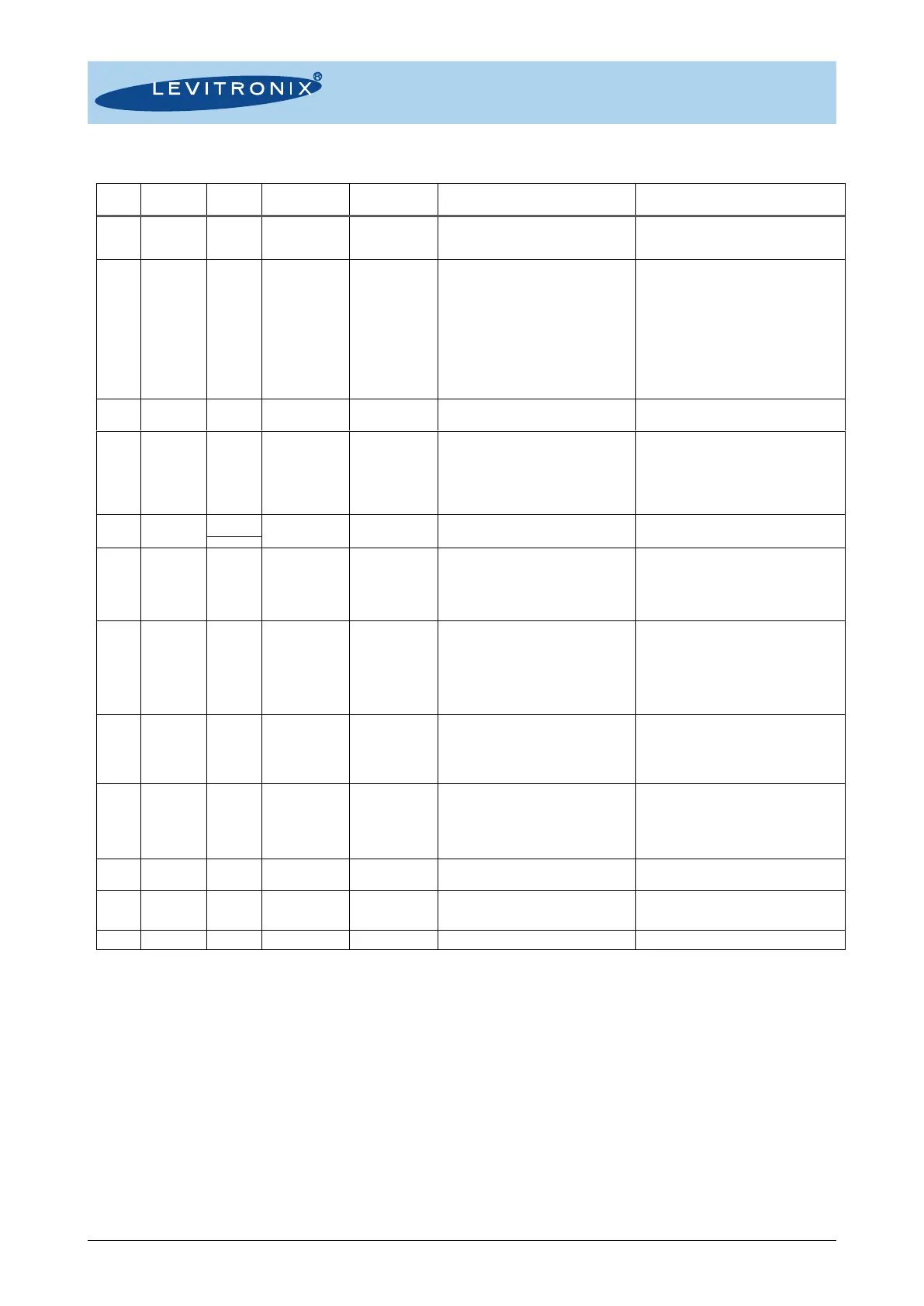
Table 13: PLC connector of EasyConnect driver mode
Note 1: Wires of compatible cables: ICS-2.1-xx Note 2: Designations for standard firmware. For other firmware refer to relevant documentation.