4.3.6 Installation of RS485 Fieldbus Multi-Pump System Arrays
Figure 32 shows a multi-pump system arrangement with the RS485 fieldbus and its basic specifications.
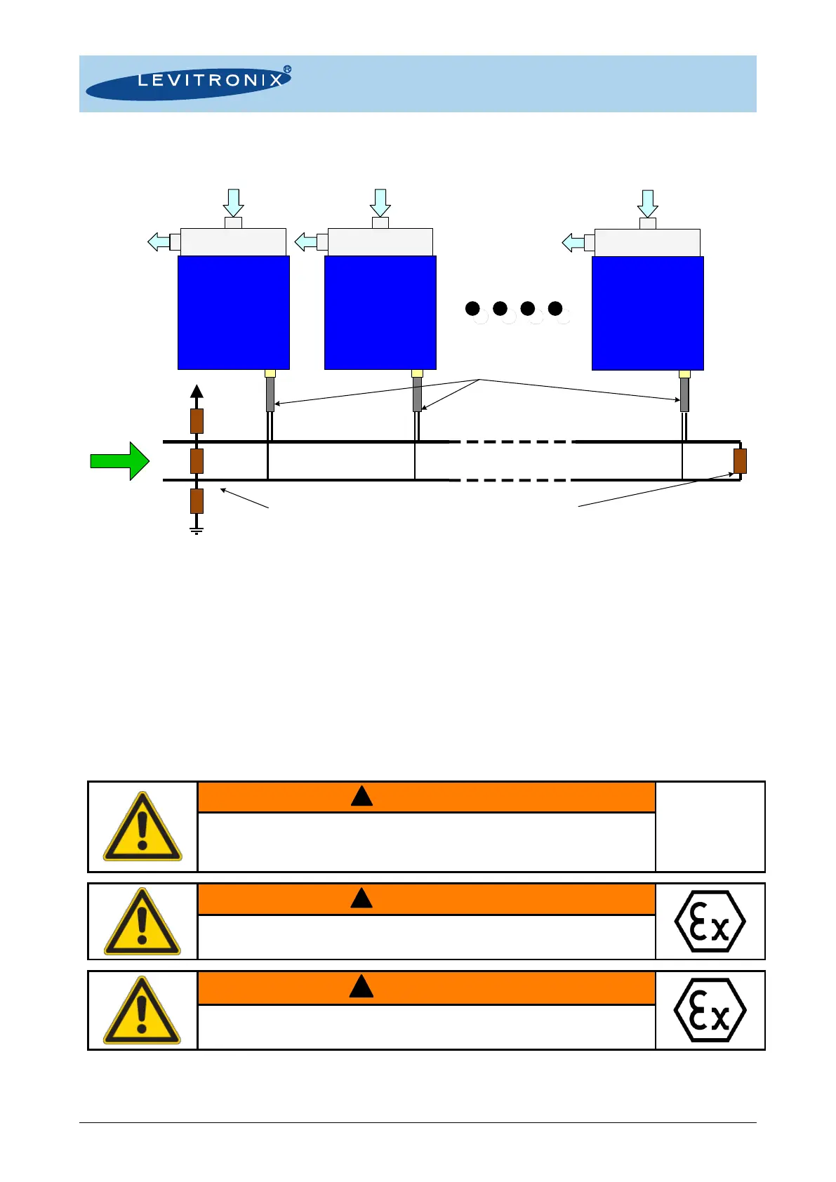
Figure 32: Multi-pump system arrangement of OEM model with RS485 fieldbus
Following points and information shall be considered:
➔ Testing has been done with arrangements of 8 pump systems. Higher number is possible but it is
recommended to contact Levitronix
®
Technical Service department (see Section 8) for details and support.
➔ Address setting of the pump units can be done with the Levitronix
®
Service Software and a PC. A
USB/RS485 converter cable with integrated initialization network can be ordered according to Table 3.
➔ The RS485 protocol for master communication is available at Levitronix
®
on request.
➔ Do not use multiple master systems at the same time.
➔ Do not use closed ring arrangements.
4.4 Mechanical Installation – General Instructions
Standard pump drivers are not rated to be placed next to flammable
gases. Do not use the driver next to flammable gases without adequate
safety precautions to fulfill the relevant regulatory requirements.
Only specific pump drivers are classified for the use in Ex classified
locations. Refer to the corresponding section in the manual.
An Ex conform solution is needed for the pump driver cable to leave the Ex area. One option is an Ex certified
cable system as listed in Table 3 and shown in Figure 9 and Figure 10.
120 120
510
510
Master
Integrated
System
#1
Integrated
System
#2
Integrated
System
#N
5V
Main Bus Line: < 100 m
Shielded cable with twisted wires recommended.
Termination:
Recommended for main bus line Length > 5m.
Initialization Network:
Always recommended.
To be implemented at the master.
Branch Bus Lines:
Length sum of all < 33 m.