4-13
Operations in Detail960L
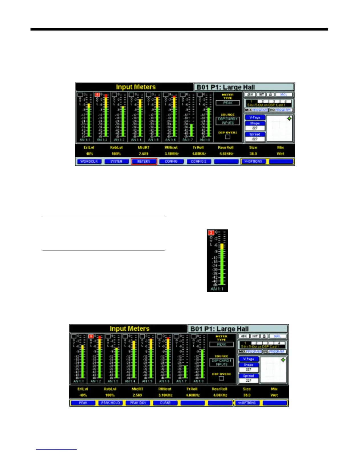
The meter screen consists of eight plasma-style meters
which show the input levels of the currently selected
machine’s DSP card.
NOTE:
If a second DSP card is installed in your system
select a machine on the second card to view the
input levels of that DSP card.
Each of the eight meters has a level indicator, a label,
and an overload (OVL) counter (Fig. 4-26).
As you can see in Fig. 4-26, the label "AN 1:1" indicates
that we are metering input type Analog 1 Channel 1. The
level indicator indicates a level of –5.5dBFS. The overload
i n d i c a t o r, labeled OVL, counts the number of
samples that have reached -0.5dBFS. Up to 99 samples
indicating an imminent overload situation will be count-
ed. In this case we have had three samples at –0.5dBFS.
When a channel overload has occurred the overload
counter box turns red and indicates the number of over-
loads; otherwise, it remains black. Pressing the Clear soft
button in the meter options will
clear the overload counters.
Three types of input metering
are available: peak, peak hold,
and peak decay. To select the
type of metering you desire ,
p ress the Options soft button
and press the metering type you
desire. The type selected is dis-
played in the meter type box to
the right of the meters.
Figure 4-25 — Input Metering Screen
Figure 4-26 — Single
DSP Input Meter
Metering Screen
Along with the simple LED Meter Bridge located above
the LCD display, a more comprehensive input metering
screen is available (Fig. 4-25). This input metering screen is
accessed when in Control mode by pressing the meter’s
soft button.
Figure 4-27 — Meter Screen with Options Selected