Do you have a question about the LG LTCS20220W and is the answer not in the manual?
Essential safety guidelines to follow before servicing the refrigerator unit.
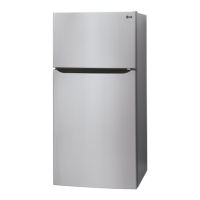
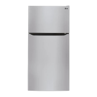
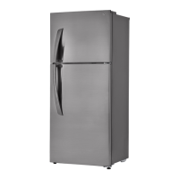
Detailed technical specifications and general features across different models.
Visual identification and listing of major refrigerator components.
Step-by-step instructions for safely removing the refrigerator door from its hinges.
Step-by-step instructions for safely removing the freezer door from its hinges.
Guide for reattaching the refrigerator door to its original position.
Instructions for reversing the swing direction of the freezer door.
Detailed steps for changing the swing direction of the refrigerator door.
Procedures for reassembling the bottom hinge components for refrigerator doors.
Steps to reattach the freezer door and secure top hinge covers.
Adjusting door alignment and unit leveling for proper closure and stability.
Guide on how to remove the fan and fan motor assembly.
Instructions for removing the defrost control assembly and refrigerator control box.
Steps for replacing the LED lighting assembly in the refrigerator.
Explains the compressor's function and the PTC-starter's role in motor starting.
Important precautions and notes for using the PTC-starter correctly.
Defines the Overload Protector (OLP) and its protective function for the compressor motor.
Provides schematic diagrams for the main control board and ice maker circuits.
Diagnostic steps for compressor and related electrical components.
Procedure for checking the resistance of the PTC-starter and OLP.
Diagnosing issues related to poor compressor performance and fan motor operation.
Troubleshooting heavy frost buildup on the evaporator and defrost heater issues.
A chart mapping complaints and symptoms to possible causes and solutions.
Troubleshooting guide based on the refrigeration cycle state and symptoms.
Methods for detecting refrigerant leaks in the sealed system.
Explains the operational sequence and principle of the automatic ice maker.
Details the functions and processes of icemaking, harvest, and fill modes.
Describes the fill/park position and how water supply amount is adjusted.
Procedures for testing the ice maker and interpreting error codes.
Explains the MICOM control functions and the automatic defrost cycle.
Details the error codes displayed for MICOM system failures.
Guide on using the test mode for diagnostics and function checks.
Instructions for activating and exiting the demonstration mode.
Identifies the layout of the main PCB and its various connectors.
Procedures for checking power supply and load circuits on the PCB.
Details the circuit for monitoring refrigerator door switches.
Explains the wiring and operation of temperature sensor circuits.
Describes the circuit responsible for powering the LED indicators.
Provides resistance and voltage specifications for temperature sensors.
Specifies the output voltage for the freezer and cooling fan motors.
Visual guide to identify and locate various case parts of the refrigerator.
Visual guide to identify and locate various parts within the freezer compartment.
Visual guide to identify and locate various parts within the refrigerator compartment.
Visual guide to identify and locate various parts attached to the refrigerator doors.
Visual guide to identify and locate various parts of the ice maker assembly.
| Child lock | - |
|---|---|
| Door hinge | Right |
| Product color | White |
| Housing material | Metal, Stainless steel |
| Reversible doors | Yes |
| Shelves material | Tempered glass |
| Appliance placement | Freestanding |
| Noise level | - dB |
| Total net capacity | 572 L |
| Total gross capacity | - L |
| Fridge net capacity | 416 L |
| Fridge number of shelves/baskets | 2 |
| Freezer position | Top-placed |
| Freezing capacity | - kg/24h |
| Freezer net capacity | 156 L |
| Storage time during power failure | - h |
| Connected load | - W |
| Annual energy consumption | 406 kWh |
| Depth | 838.2 mm |
|---|---|
| Width | 736.6 mm |
| Height | 1676.4 mm |
| Weight | 91600 g |