40
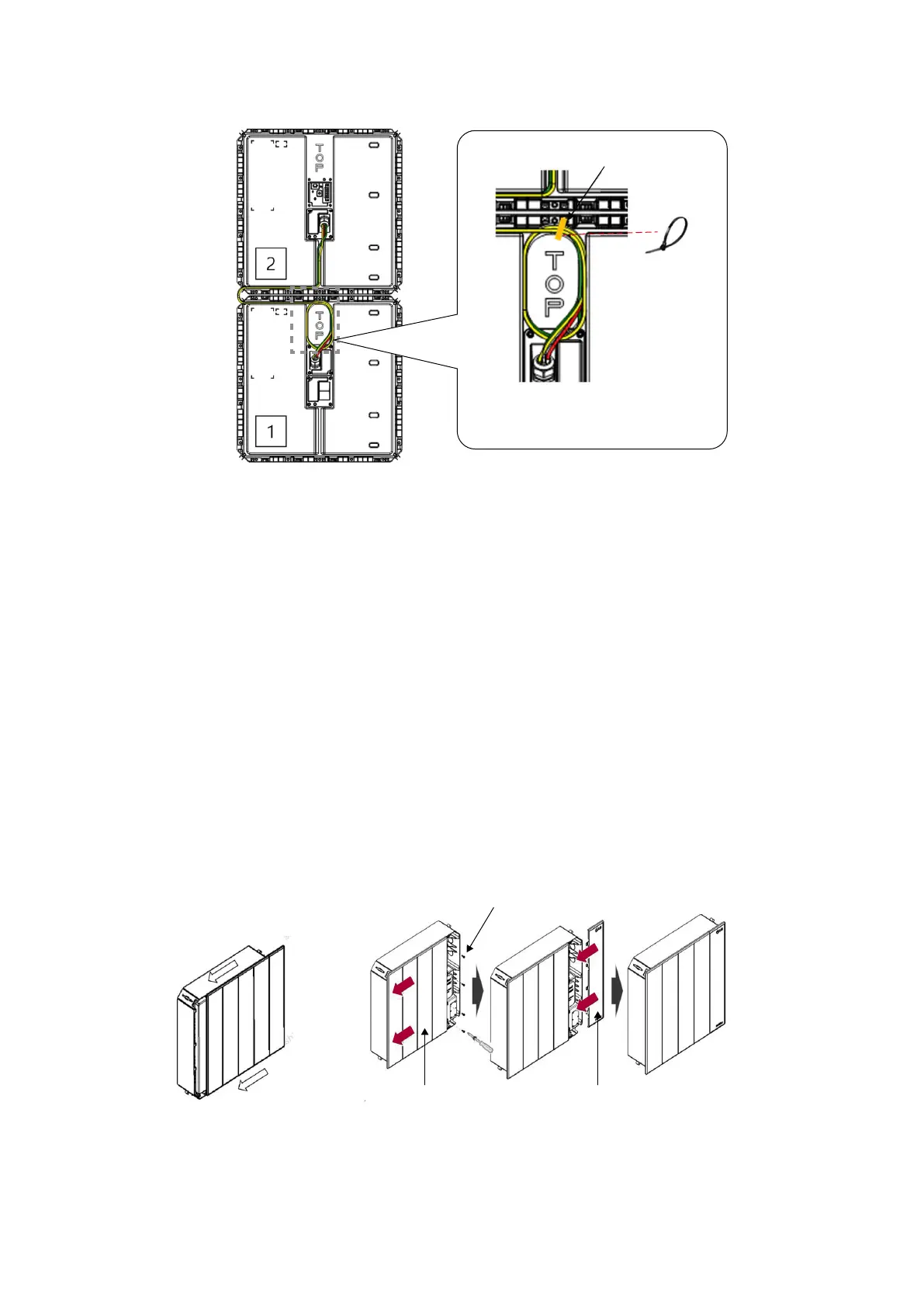
3) Bottom to top connection
Tie hole
Cable Tie
The excess wire length should be
fixed as shown in the figure
3.7.5 Finalizing Installation
The following steps shall be executed after the connection to the inverter
and commissioning is completed.
1. Attached Design Cover to all BMAs by sliding it from right to left.
2. Replace the Design Cover of the BPU by sliding it from right to left.
3. Fasten the 4 bolts that were removed.
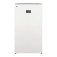
4. Replace the LED Cover of the BPU by sliding it backwards.
LED CoverDesign Cover
<BMA cover> <BPU cover>
M6 Bolt
(a torque of 1.5 N·m)