24
4 - OPERATIONAL PARAMETERS
AND YARN CONSUMPTION KIT
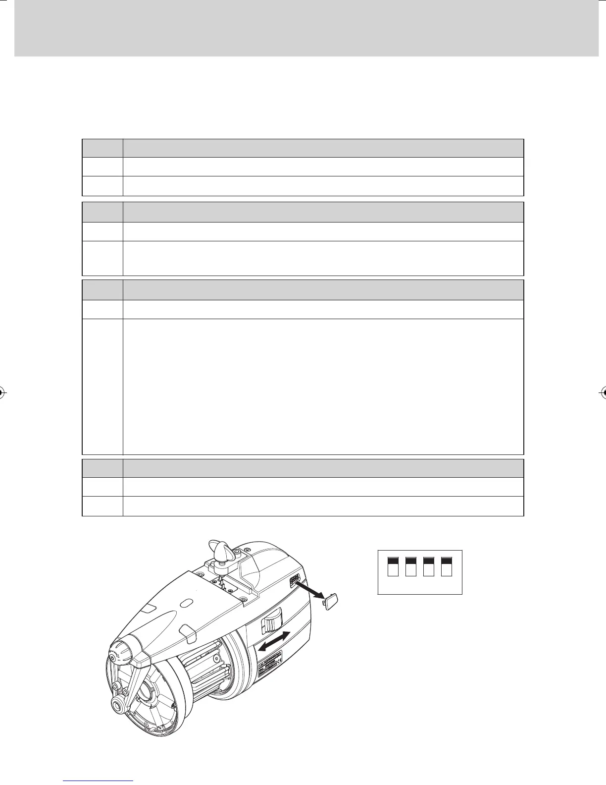
4.1 DIP-SWITCH SETTINGS
Access to the DIP-SWITCH is enabled by snapping off side cap (D) located
on the feeder housing.
Standard optical sensor sensitivity.
Increased optical sensor sensitivity, set when
operating with yarn counts thinner than 40 den.
OFF
ON
DS2 SETTING MEANING
(Default Position = OFF)
Work position (standard)
Self-calibration of magnetic sensors.
The recommended procedure is stated below:
- Set switch 0-1 to 0. Set DS3 to ON.
- Remove the yarn reserve from the spool body,
keeping the feeder threaded.
- Set switch 0-1 to 1. The feeder winds the reserve laying down a fixed
number of turns on the spool body
-
If the procedure has been correctly performed, the feeder will put the indicator
lamps on for one second to indicate that calibration has been correctly performed.
OFF
ON
DS3 SETTING MEANING
(Default Position = OFF)
Z Rotation
S Rotation
OFF
ON
DS1
SETTING MEANING
(
Default Position = OFF)
Bus termination off.
Bus termination on (see paragraph 4.2).
OFF
ON
DS4
SETTING MEANING
(Default Position = OFF)
Note: To enable the function
performed by each Dip-Switch, the
feeder needs to be switched off by
acting on switch 0-1; then set the
Dip-Switch to the desired position
and switch the feeder on again.