8
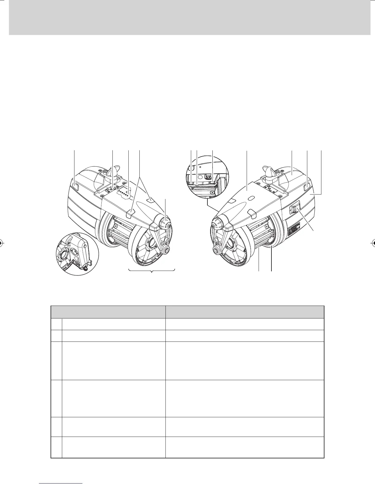
1.1 MAIN PARTS – CONTROL AND ADJUSTMENT POINTS
Main Parts:
1 • MOTOR 6 • OPTICAL OUTPUT SENSOR
2 • TOP PANEL 7 • POWER CABLE CONNECTION
3 • FLYWHEEL 8 • MAIN ELECTRONIC CONTROL BOARD
4 • YARN SPOOL BODY 9 • WINDING RESERVE CONTROL FEELER
5 • OUTPUT TENSIONER UNIT 10 • INPUT FEELER
1 - GENERAL FEATURES
0 – I SWITCH
SERIAL COMMUNICATION PORT
SIGNAL LAMPS
DIP SWITCH
ADJUSTING TWIST-KNOB
THREE-WAY CONNECTOR
• Switches the yarn feeder ON and OFF.
• Enables Pocket and PC interfacing.
• If yarn feeder is turned on and there are
no malfunctions, they will not light up.
• They will light up if any malfunction arises.
(consult paragraph 9 “Trouble shooting”).
• Enables adjustment of the optical sensor’s sen-
sitivity range, reverse the direction of rotation,
self-calibrate magnetic sensors and perform the
termination of the serial bus (see chapter 4.1).
• Enable adjustment of the outbound yarn
tensioning.
• Enables connection of an output yarn feeler
(see chapter 1.8).
A
B
C
D
E
F
CONTROLS / ADJUSTMENTS FUNCTION
FOR FURTHER DETAILS CONCERNING
THE ATTIVO ELECTRONIC TENSIONS,
PLEASE GO TO CHAPTER 7