Chapter 2 - Operating Instructions 7200 Series UPS User Manual
Introduction Single Module and 1+1 Parallel System
document in response to "powersure ups"
Page 2-2
Issue 6
(03/98)
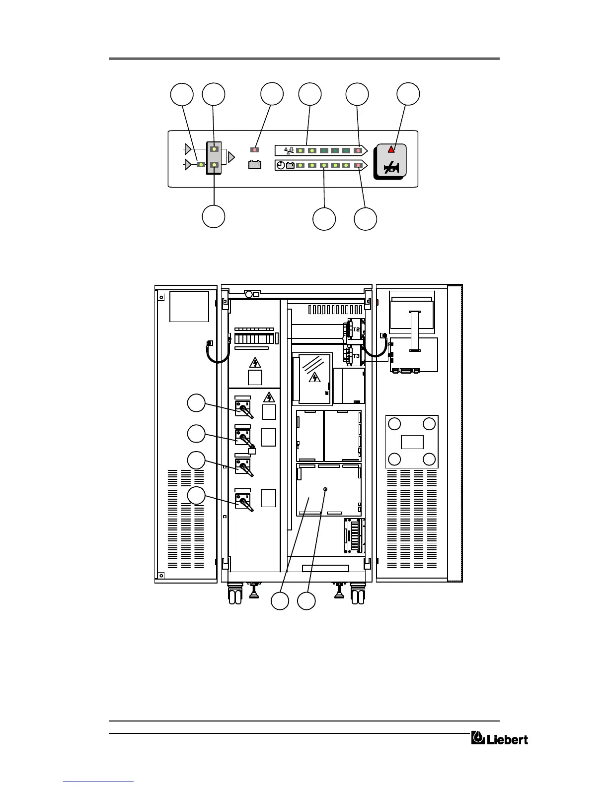
A = ( Q1 ) Rectifier input power switch
B = ( Q2 ) Static Bypass input power switch
C = ( Q3 ) Maintenance Bypass power switch
D = ( Q4 ) UPS output power switch
1 = Reset push-button
2 = UPS Logic Board
%
3
1
2
4
5
7
9
6 8
Figure 2-A . LED indications
D
C
B
A
2 1
455007H
45
2
0
07
4
A
4530025T
4
5
03
0
28
K
455005F
45
0
30
3
0M
Figure 2-B . Power Switch identification


 To Next Page