Chapter 6 - Trouble shooting 7200 Series UPS User Manual
Dispaly panel message interpretation Single Module and 1+1 Parallel System
document in response to "powersure ups"
Page 6-4
Issue 6
(03/98)
6.3 Display panel message interpretation
The messages displayed on the 7200 can be categorized into two types; (a) ALARM messages these
are messages which need urgent attention and warn of a UPS shutdown or imminent shutdown the load
would normally transfer to the bypass supply if it is available. All alarm messages are accompanied by
an audible warning. (b) WARNING messages these are messages generated to warn or confirm to the
operator of actions taken ( i.e. if the rectifier a.c. input supply power switch was opened the Warning
message would read RECTIF. SWITCH OPEN ).
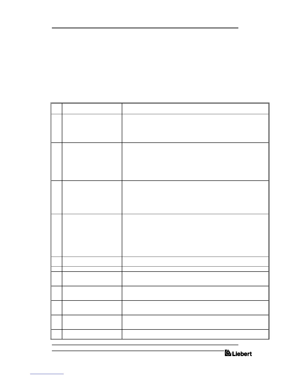
The following table lists the various messages displayed on the operator panel together with a
description of their interpretation.
DISPLAY ALARM
MESSAGES
INTERPRETATION
1 EMERGENCY STOP This alarm indicates that the UPS was shut down by means of the local or remote (if
fitted) Emergency Power Off push button ( EPO ) which is normally due to operator
action - investigate why the emergency power off push button was pressed.
If the emergency power off push button was not pressed then check the continuity of
the circuit to the remote switch. Customer connections; auxiliary terminal block X3;
pins 10 and 11; normally closed.
2
3
INV.: OFF
INV.: OVERVOLTAGE
INV.: UNDERVOLTAGE
OUTPUT: NO VOLTAGE
OUTPUT: WAVEFORM ERR
The INV.: OFF alarm is active whenever the inverter is not producing its correct
output voltage; either because it has been switched OFF or due to an internal fault, it
will normally be accompanied by one or more of the other inverter fault conditions.
Most of the inverter fault messages are self explanatory however the WAVEFORM
ERR. informs the operator that the output voltage peak has flattened caused by an
internal inverter problem and therefore the output will be out of limits.
4
5
INV.: OVERTEMPER.
OVERTEMP. SHUTDOWN
Over temperature is sensed by a normally-close thermostat ( 90
o
C operating ) fitted to
each inverter heat sink. If an over temperature condition arises, the audible alarm will
accompany this message: the inverter stops and load transfers to bypass after 3
minutes.
This message informs the operator that the inverter has been switched off and that the
load has been transferred to bypass due to an inverter over temperature.
6
7
OVERLOAD PRESENT
OVERLOAD SHUTDOWN
The inverter overload has an inverse load/time characteristic – i.e. it will accept 125%
overload for 10 minutes and 150% for 60 seconds. If this characteristic is exceeded
then the load transfers to the bypass supply, the inverter stops and the overload alarm
annunciates. The [OVERLOAD PRESENT] alarm will annunciate as soon as the load
exceeds 100% of the UPS rating,, and the load will transfer to bypass some time later
–depending on the degree of overload present.
This message informs the operator that the load has transferred to bypass due to an
inverter overload.
8 OUTPUT SWITCH OPEN This is a status alarm. The output switch must be selected `CLOSED' at all times
except when operating on the maintenance bypass supply
9 BYPASS SWITCH OPEN This is a status alarm. The bypass input switch must be closed at all times.
10 BATTERY C.B. OPEN This is a status indication only. Note that if the UPS is operating with the battery
circuit breaker open and the mains power fails then the UPS output will also fail
together with load power, since the inverter has no battery back-up.
11 BATTERY: FUSE FAIL This problem should be rectified as soon as possible. If the mains power fails then the
UPS output will also fail together with load power, since the inverter has no battery
back-up.
12 BATTERY: TEST FAILED The system has carried out a test of the battery. If this alarm is not accompanied by a
[BATTERY C.B. OPEN] or [BATTERY: FUSE FAIL] message then a full check of
the battery bank is required
13 DC BUS: UNDERVOLTAGE When the inverter is operating on the battery this message is displayed when the
battery voltage has fallen below a preset value. If the input a.c. power cannot be
restored you should shut down your loads.
14 BATTERY: E.O.D. Battery discharge has continued beyond a preset value. The inverter will have shut
down, the system will attempt a transfer to bypass: if there is no bypass supply


 To Next Page