Chapter 7 - 1+1 Parallel System 7200 Series UPS User Manual
Installation procedure (Separete batteries) Single Module and 1+1 Parallel System
document in response to "powersure ups"
Page 7-4
Issue 6
(03/98)
7.2 Installation procedure (Separete batteries)
Installation procedure is basically the same as for single module, so
read and apply instructions of Chapter 3 - Installation Procedure of
this User Manual.
Differences are shown below.
7.2.1 Preliminary Checks
Be sure that the option parallel kit is present and connected for both
modules, that they are the same size and with the same SW and HW
release.
WARNING
Operation of fitting the parallel kits and setting of boards and UPS to
convert it from Single Module to 1+1 must be made by Liebert Service &
Support trained personnel.
This operation involves also setting of system with:
separate batteries or common battery, 1+1 redundant or full power
7.2.2 Power cables
Input Bypass and Rectifier, outputs of modules
As shown in fig. 7-1 and 7-2, to achieve maximum flexibility, is suggested to use separate isolators and
protections for each module: in this case rating of cables is the same as for single module.
As for single module, it’s suggested to use a power isolators at the output of each module: this power
isolators connected at the output of UPS is only for plant maintenance:
it must not be used for protection of UPS output or cabling
this protection is deemed to input bypass line breaker and current limit of inverter.
The cross section and lenght of the cables on the bypass line and on the output of the two UPS modules
should de equal, to ensure the balance of the currents when the load is supplied by the bypass mains.
Battery
4
5
0
3
0
3
0
M
4
5
0
3
0
2
8
K
4550007H
4
5
3
0
0
2
4
S
4
5
2
0
0
7
4
A
4520075B
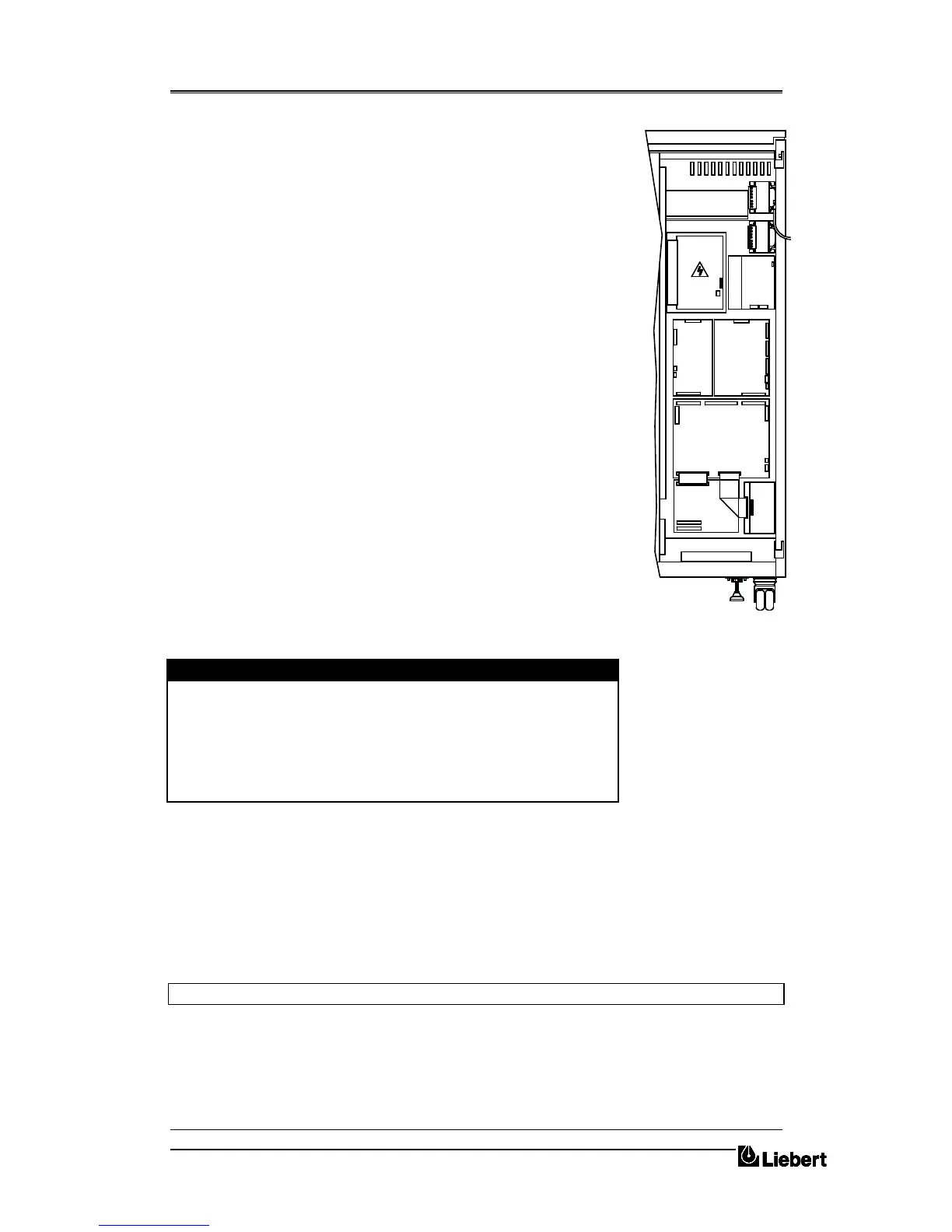
Figure 7-C Position of parallel option


 To Next Page