Chapter 4 - Optional equipment 7200 Series UPS User Manual
Remote Alarm Monitor (RAM) (4305001Z) Single Module and 1+1 Parallel System
document in response to "powersure ups"
Page 4-6
Issue 6
(03/98)
4.4 Remote Alarm Monitor (4305001 Z)
When used in conjunction with the Interface board described previously, the Remote Alarm Monitor
enables the auxiliary alarm signals to be displayed at a remote station up to 100 meters from the main
equipment.
The RAM, which can be mounted either horizontally or vertically, contains a mains-driven power
supply for alarm LED annunciation and displays the following warnings:
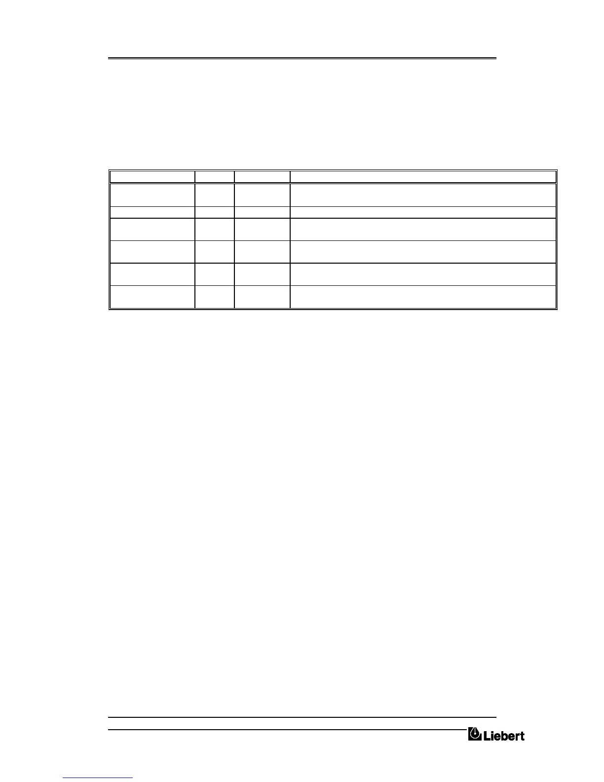
Panel Colour Normal state Interpretation
INVERTER ON green ON Normal operating condition indicating that the load is being supplied by
the inverter. This is not an `alarm' indicator.
UTILITY FAILURE red OFF When lit, it indicates that the input bypass is out of tolerance or missing.
BATTERY LOW red OFF When lit, it indicates that the battery voltage is below minimum or that
the battery circuit breaker is open.
BYPASS ON red OFF When lit, it indicates that the load is being fed from the bypass supply,
possibly due to a UPS failure.
BYPASS
MAINTENANCE
red OFF When lit, it indicates that the UPS has been selected to operate on the
maintenance bypass and the load is unprotected
ALARM red OFF This is a `common alarm' and is lit when any of the red leds described
above are lit.
Table 4-A
An audible warning accompanies any of the above alarm conditions. This is, however, subject to a
short time delay when activated in conjunction with the `Utility Failure' and `Bypass ON' alarms, to
prevent the warning being activated by transient conditions. Pressing the `reset' push-button cancels the
audible warning but the alarm indications remain until the condition is rectified.
4.4.1 Connections
Power supply
The RAM contains a single phase 220-240 V a.c. mains-driven power supply. Power is applied
through a standard three-pin mains connector located in the RAM back panel (plug provided) use
3-core 0.5 mm
2
cable (minimum). The supply is rated at approximately 4 Watts and fused at 1A.
It is advised that the power supply is taken from the UPS output, otherwise in the event of a mains
failure the RAM may be inoperative.
Alarm connections
A 9 pin D-type connector with solder points is provided with the RAM. This connector fits into the 9
pin socket on the back of the RAM and should be cabled to the Interface Board (4590055 P), fitted to
the UPS, using 9 core, 0.22 mm. (minimum) shielded cable as shown. The maximum recommended
distance is 100 meters.


 To Next Page