pag. 2
IMPORTANT:
The bulb must be positioned as much outside as possible but
must not be exposed to direct sunlight or weather agents
such as rain or snow. The unit operation could be jeopardized
if these precautions are not applied.
2.5 --- Positioning the HPSC condensing
unit
Available condensing unit versions:
HPSC “0”: base version
HPSC “A”: advanced version
HPSC “L”: long piping version (see Fig. 12)
S The condensing unit must be positioned outside to en-
able its cooling (see Fig. 3).
S It is connected to the air conditioner through the re-
frigerant pipelines. Keep the refrigerant lines as short
as possible and anyway follow the indications in
Tab. a, Tab. b, Fig. 11 and Fig. 12, considering that in-
stallations with equivalent length of the refrigerant
pipelines over 10 m are possible only for HPSCxxL
units.
S Install the condensing unit in a level position, able to bear
its weight and vibrations and away from contaminating
agents (e.g. dust, leaves) to ensure the best efficiency
over time. Avoid any place containing flammable gases.
S If different locations are available, preferably install the
condensing unit in places sheltered from rain, with suit-
able air circulation and not subject to strong sun expo-
sure; the latter precaution enables performance opti-
misation and compliance with the operating limits. For in-
stallationsinplaceswithwindspeedsover5m/s(e.g.
building tops) consider that such conditions can offer re-
sistance to the air outlet from the condensing unit, reduc-
ing the air delivery and thus the heat exchange capacity,
or they can make the fan run too fast jeopardizing its oper-
ation, as well as increasing the hazard of the machine tilt-
ing if it is not properly fixed. To lessen the problem of
strong gusts of wind, position the condensing unit close
to a wind barrier (e.g. building or enclosing wall) and in
a direction perpendicular to the flow of the discharge air.
To prevent tilting ensure that the unit is securely fixed, if
necessary through additional supports or tie---rods, thus
ensuring stability even in case of earthquakes. Position
the unit so that the ejected hot air and the sound
emissions do not disturb people. In case of snow, make
sure that the unit is not completely covered and that the
inlet sections are always clear. To enable sufficient air de-
livery through the unit/s and to have sufficient space for
maintenance, it is necessary not to obstruct the air inlet
and discharge sections of the condensing unit, position-
ing it, or several machines, to maintain the minimum ser-
vice areas and distances indicated in Fig. 4, for some
possible installation configurations.
S Fig. 3 shows some examples of how to install the con-
densing unit. For wall---mounted installation the con-
densing unit can be supplied with an optional mounting
kit, comprising a pair of galvanised steel angle brackets,
painted with RAL9002 polyester powder with a smooth
finish; suitable elastomer anti---vibration mounts and
stainless steels fixings, including anchor screws for wall
fastening (see Fig. 2d).
NOTE: The anchor screws included in the kit are to be
used only when fastening the brackets to a concrete or
brick wall (including hollow bricks). Do not use them on
sandwich walls (e.g. a container) or walls of unknown
composition. In these cases the most suitable fastening
system for the special material must be used. If the above
mentioned optional kit is not used, suitable anti---vibra-
tion mounts must always be fitted between the condens-
ing unit and the mounting brackets, to avoid the trans-
mission of vibrations. Also make sure that the brackets
used are suitable for supporting the condensing unit in all
conditions (e.g. in case of temporary abnormal loads on
the unit).
2.6 --- Refrigeration connections
THIS OPERATION MUST BE CARRIED OUT BY AN EX-
PERT TECHNICIAN.
The condensing and evaporating units are pre---charged
with Nitrogen and have to be charged with refrigerant (see
Chap. 7.2.2 – Refrigerant charging).
a) Pipeline positioning
Connect the air conditioner to the condensing unit using re-
frigerant lines in hard or soft copper.
S Limit the number of pre---shaped bends. If this is not
possible, every bend must have a radius of at least 100
mm.
S The gas line must be insulated.
S The liquid line must be kept away from heat sources. If
this is not possible it has to be insulated.
S If the condensing unit is located above the evaporating
unit, the last segment of the suction line (insulated pipe-
work) must be inclined towards the condensing unit.
If, on the other hand, the condensing unit is located below the
air conditioner it is advisable to create a trap on the suction
line.
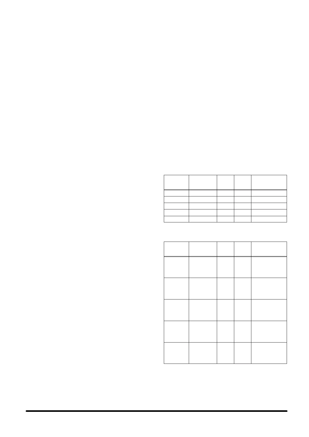
Tab. a --- HPSCxx0/A: external standard
diameters for external refrigerant
pipelines --- R407C
Model
Equivalent
length
“L”
Gas
line
Liquid
line
Cooling capacity
drop vs. the std.
installation (2m)
HPS060/A 2m<L≤10m φ 16 x 1 φ 12 x 1 1% with 10 m
HPS080/A 2m<L≤10m φ 16 x 1 φ 12 x 1 3% with 10 m
HPS100/A 2m<L≤10m φ 18 x 1 φ 12 x 1 2% with 10 m
HPS120/A 2m<L≤10m φ 18 x 1 φ 12 x 1 4% with 10 m
HPS140/A 2m<L≤10m φ18x1 φ 12 x 1 5% with 10 m
Tab. b --- HPSCxxL: external standard diameters
for external refrigerant pipelines---R407C
Model
Equivalent
length
“L”
Gas
line
Liquid
line
Cooling capacity
drop vs. the std.
installation (2m)
HPS06L
2m<L≤10m
10m<L≤20m
20m<L≤30m
30m<L≤40m
40m<L≤50m
φ 16 x 1
φ 16 x 1
φ 18 x 1
φ 18 x 1
φ 18 x 1
φ 12 x 1
φ 12 x 1
φ 12 x 1
φ 12 x 1
φ 12 x 1
1% with 10 m
4% with 20 m
3% with 30 m
5% with 40 m
6% with 50 m
HPS08L
2m<L≤10m
10m<L≤20m
20m<L≤30m
30m<L≤40m
40m<L≤50m
φ 16 x 1
φ 18 x 1
φ 18 x 1
φ 18 x 1
φ22x1
φ 12 x 1
φ 12 x 1
φ 12 x 1
φ 12 x 1
φ 16 x 1
3% with 10 m
3% with 20 m
5% with 30 m
6% with 40 m
3% with 50 m
HPS10L
2m<L≤10m
10m<L≤20m
20m<L≤30m
30m<L≤40m
40m<L≤50m
φ 18 x 1
φ 22 x 1
φ22x1
φ22x1
φ22x1
φ 12 x 1
φ 12 x 1
φ 16 x 1
φ 16 x 1
φ 16 x 1
2% with 10 m
3% with 20 m
5% with 30 m
6% with 40 m
7% with 50 m
HPS12L
2m<L≤10m
10m<L≤20m
20m<L≤30m
30m<L≤40m
40m<L≤50m
φ 18 x 1
φ22x1
φ22x1
φ22x1
φ28x1
φ 12 x 1
φ 16 x 1
φ 16 x 1
φ 16 x 1
φ 16 x 1
4% with 10 m
3% with 20 m
4% with 30 m
5% with 40 m
2% with 50 m
HPS14L
2m<L≤10m
10m<L≤20m
20m<L≤30m
30m<L≤40m
40m<L≤50m
φ18x1
φ22x1
φ22x1
φ28x1
φ28x1
φ 12 x 1
φ 16 x 1
φ 16 x 1
φ 16 x 1
φ 16 x 1
5% with 10 m
3% with 20 m
5% with 30 m
2% with 40 m
3% with 50 m