pag. 3
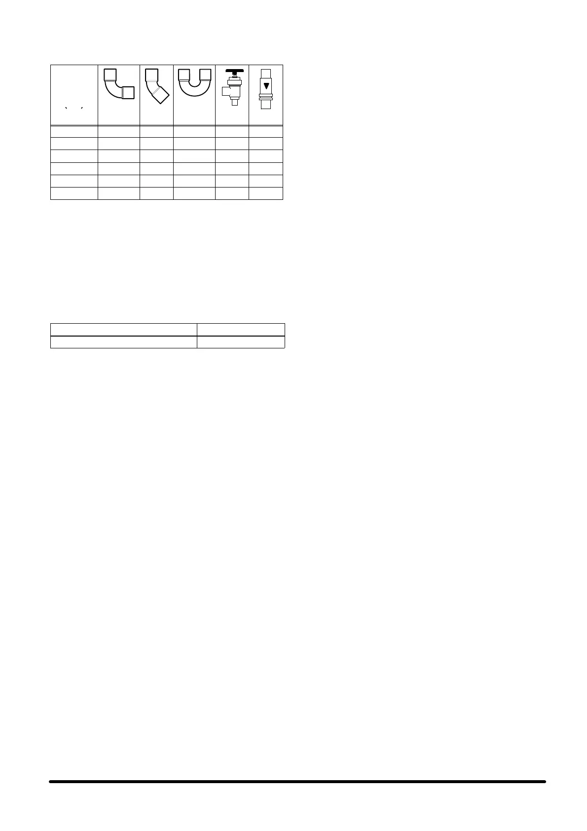
Tab. c --- Equivalent lengths (m) of: curves,
shut---off and non---return valves
Nominal
diameter
(mm)
90° 45° 180° 90°
12 0.50 0.25 0.75 2.10 1.90
14 0.53 0.26 0.80 2.20 2.00
16 0.55 0.27 0.85 2.40 2.10
18 0.60 0.30 0.95 2.70 2.40
22 0.70 0.35 1.10 3.20 2.80
28 0.80 0.45 1.30 4.00 3.30
b) Evacuation of the refrigerant lines
The evacuation operation must be carried out with a special
(quality) vacuum pump, using the 1/4” SAE connectors, lo-
cated on the unit on---off valves,
2.7 --- Condensate drain connection
During the cooling cycle part of the moisture in the air con-
denses on the evaporating coil. The condensate is collected
in the tank fitted under the coil and must be drained outside.
Tab. d --- Condensate drain connection
CONNECTOR DIMENSIONS
Condensate drain φ 21 mm
To drain the condensate:
S Use galvanized steel, P VC or flexible polythene pipe.
S CAUTION: DO NOT INTERCONNECT THE OUTLETS OF
DIFFERENT MACHINES.
S Make sure there is at least a 2% gradient towards the
drain outlet.
S There must beadraintrapplacedatleast30mmbelow
the drain tank.
S Fill the drain trap with water by pouring it into the conden-
sate tank.
2.8 --- Electrical connections and wiring
diagram (supplied with the unit)
For the electric connections of the indoor units HPSE and
outdoor units HPSC, refer to Fig. 5, Fig. 6 and Fig. 7.
Before connecting or disconnecting the fast couplers be-
tween the indoor unit and outdoor unit, make sure that the
main switch is in the “OFF” position and that:
S all electrical components are not damaged;
S allterminalscrewsaretight;
S thesupplyvoltageandfrequencyareasindicatedonthe
unit;
S there are no live components.
IMPORTANT:
The 48 Vdc supply (in the version ”Emergency Free Coo-
ling”) must be delivered through a shielded cable, with the
connection of the shielding braid on the evaporating side.
The signal connection cable between the evaporating unit
and the condensing unit must be shielded, with the connec-
tion of the shielding braid on the evaporating side.
2.9 --- User interface
The standard control system on HPS is based on a micropro-
cessor board mounted inside the electrical panel, which can
be connected to a user interface (remote display) that can be
positioned inside the room as required. The user interface
(remote display), when installed, is mounted in a painted
metal box and connected to the air conditioner using a
multi---pole screened cable (optional accessory).
2.10 --- Emergency cooling version
(EFC 48 VDC / 230 VAC)
When this option is used install the supply cable as described
in the electrical diagram.
In the 48VDC units respect the polarity “+” and “---”.
2.11 --- Electrical protection
CAUTION: For the electrical protection of the conditioner an
adequate switch with current protection must be installed in
the power supply line. For the selection of the disconnect
switch please refer to Tab. 7.
3 --- Starting and stopping
3 . 1 --- F i r s t s t a r t --- u p
(or after a long halt)
Before starting the air conditioner check if the power supply
voltage and frequency comply with those on the identifica-
tion plate of the unit. After this, it is possible to power the unit
by operating the main switch. For units equipped with Power-
Face microprocessor control, it is possible to start and stop
the unit by following the instructions given below.
For units equipped with POWERFACE interface only:
S The unit is started by pressing the main switch ON.
S The unit is stopped by pressing the main switch OFF.
For units equipped with a local or remote display interface:
S The unit is started by pressing the switch with LED.
S The unit is stopped by pressing the switch with LED.
For units supplied with a HIROMATIC interface:
S Start by pressing the ON---OFF push button on the Hiro-
matic (confirmed by SYS.ON on the display).
S Stop by pressing the ON---OFF push button on the Hiro-
matic (confirmed by SYS.OFF. on the display).
IMPORTANT:
In both cases it is extremely important to consider the status
of the digital input to the PowerFace microprocessor control
managing the unit ON---OFF (see relevant handbook and wir-
ing diagram). Indeed, for the unit to start (operating on the
unit main switch, or on the ON---OFF button of the HIROMA-
TIC interface), the digital input must be bridged (see wiring
diagram). Check that there are no active alarms; wait until the
system reaches the standard operation and then make the
following checks:
S Check that the fans are working correctly.
S Make sure that the temperature is controlled and the
compressor and the heaters (optional) work when re-
quired.
S Make sure that the condensing unit fan speed controller
regulates the fan operation (only on “HPSCxxA/L” mo-
dels).
3 . 2 --- S t a r t --- u p w i t h l o w o u t s i d e t e m p e r a -
ture (only on “HPSCxxA/L” models)
In case of low outside temperature (<0_C), the unit start---up
is helped by the delay time of the low pressure alarm, within
which the pressures in the refrigerating circuit reach the stan-
dard operation values.
3 . 3 --- S e l f t e s t
The self---test function is possible only when a unit has the re-
mote or local display installed. The self---test function, per-
forms a sequential, automatic check of components such as
the compressor, fan, heaters, Freecooling damper, alarm
relay and warning relay. This eliminates the need for manual
control and leads to a remarkable decrease in the time
needed for starting the unit, with the ability to carry out a quick
check of the main components for the correct conditioner
operation.