2. Installation DVI-OPT-220-Pro series – User's Manual 8
Connecting Steps
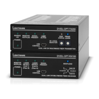
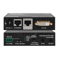
DVI-OPT-TX220-Pro
OPT
Confidence monitor
Power
Power
RS-232
DVI
POWER
SOURCE CONNECTED (pin14 +5V)
LASER ACTIVE
DVI INPUT SIGNAL PRESENT ENTER
DVI Multimode Fiber TransmitterDVI-OPT-TX220-Pro
PC
DVI
DVI Multimode Fiber Receiver
DVI-OPT-RX220-ST-Pro
MONITOR 2 HOTPLUG
DVI SIGNAL PRESENT
MONITOR 1 HOTPLUG
GREEN: LASER DETECTED
RED BLINKING: LOW LASER LEVEL
POWER
Projector
DVI
Power
Power
DVI-OPT-RX220-Pro
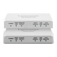
Transmitter side Receiver side
an LC optical cable to the Channel A LC
connector, or use a Neutrik opticalCon Duo
cable.
Connect the DVI source (e.g. PC) to the
DVI INPUT connector.
Optionally connect a display device to the
LOCAL MONITOR OUTPUT connector.
Connect a straight serial cable to the
RS-232 LOCAL CONTROL and the PC in
order to control the transmitter.
connected display devices. They will
display the picture from the DVI source
(computer).
cable to the FIBER INPUT connector.
Connect an LC optical cable to the
Channel B LC connector, or use a
Neutrik opticalCON Duo cable.
Connect the DVI display devices to the
DVI OUTPUT connectors.
See the powering options in the next
section.
WARNING! Please do not look directly into
connected to the transmitter only and the laser
is active.
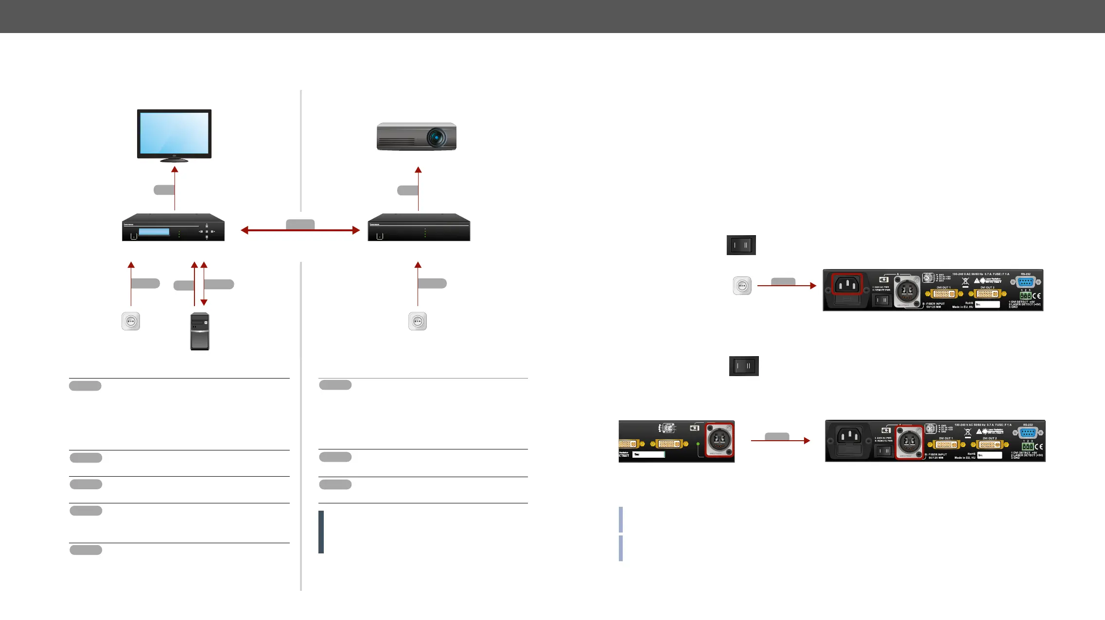
Powering Options
them. Powered on devices may have dangerous voltage levels, that can damage sensitive electronic circuits.
Transmitter
After the system is complete, connect the IEC power cable to the extender unit and then to the power outlet.
The unit is immediately powered on.
After the extender units are initialized, the attached DVI source and monitor can be powered on.
Receiver
Two power source can be chosen to supply the receiver unit:
To use the built-in power supply
To power the unit remotely
INFO: The laser becomes enabled any time the transmitter is powered on, disregarding that it was disabled
before or not. This is done to avoid accidental laser loss problems.
INFO: If neither the LEDs nor the LCD light up upon power-up, the unit is most likely damaged and further
use is not advised. Please contact support@lightware.com.
Power
Connect IEC Power Cable
2
Set the power selector
switch to I (only on
DVI-OPT-RX220-Pro)
Connect a DVI-OPT-TX220-Pro
with Neutrik hybrid fiber cable
2
Set the power selector
switch to II (only on
DVI-OPT-RX220-Pro)
Power
A
B
LOCAL MONITOR OUTPUT
Remote power for receiver DC OUT +15V
GND
Remote power for receiver DC OUT +15V
GND
LASER
ACTIVE
FIBER OUTPUT (A):
50/125 MULTIMODE
B
A
Laser Radiation
850 nm, Class 3