Do you have a question about the LIMBACH L 2000 Series and is the answer not in the manual?
The title of this manual is: Installation Manual for the LIMBACH L 1700, L 2000 and L 2400 Series Engines.
Describes installation requirements, mandatory requirements, and recommendations for LIMBACH aircraft engines.
This manual applies to LIMBACH L 1700, L 2000, and L 2400 engines, covering L 2000 series and L 2400 EF engines.
Manual is protected by copyright; reproduction in any form requires permission.
Provides definitions and illustrations for cylinder designation, direction of rotation, and engine interfaces.
General description of the cooling system requirements for LIMBACH engines.
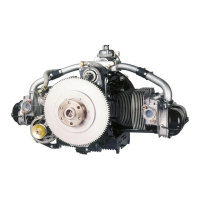
Details air cooling for L 1700, L 2000, and L 2400 EB series engines, including cowling and baffle requirements.
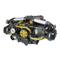
Details the cooling system for the L 2400 EF engine, featuring liquid-cooled cylinder heads and air cooling.
Describes air cooling for cylinders, specifying requirements for air quantity and pressure.
Lists components for cylinder-head cooling: coolant pump, pipes, hoses, radiator, and expansion vessel.
Explains the oil cooling system, requiring a radiator or heat exchanger and specific ducting.
Provides technical specifications for coolant flow, max coolant temp, radiator size, and air speed.
Describes generator cooling to prevent diode plate overheating and pre-cooling for the oil cooler.
General fuel system requirements: fuel types, chemical resistance, filters, and water traps.
Fuel system requirements for L 2000 series: filter capacity, mechanical and electrical pump usage.
Illustrates a sample fuel system layout and its component symbol designations.
Details constant depression carburetors and recommends carburetor heating systems for L 2000 series.
Details the fuel system for the L 2400 EF engine, including electric pumps and pressure regulator.
Lists L 2400 EF fuel system components: pipes, pumps, pressure regulator, and fuel lines.
Explains the L 2400 EF fuel loop circuit for injection, tank function, and pump operation.
Describes the air filter's function, ducting, and importance for engine protection.
Overview of the electrical system, highlighting starter power output and cable cross-section.
Details the 12V electrical system for L 2000 series engines, including battery capacity and starter cable size.
Describes the 12V electrical system for the L 2400 EF engine with electronic management.
Details the L 2400 EF's electronic engine management system, fuel, and ignition control.
Explains connecting engine electrics, including ECU, wiring looms, and sensors.
Instructions for mounting the ECU with shock mounts and routing cable looms.
Details the division of engine cables into three looms and their specific connections.
Explains how the relay-box (MCU) supplies electrical power to engine systems.
Provides steps for testing the MCU connection using a diode test meter.
Describes how to perform functional tests on the MCU and emergency battery.
Lists available sensors and instruments for engine monitoring, including part numbers.
Provides calibration procedures for EGT, water temperature, oil pressure, and oil temperature instruments.
Details the pin assignments and connections for the RPM indicator with a 9-pin connector.
Explains how to connect the RPM indicator using a generator pickup.
Details sensor pin connections for oil pressure and oil temperature instruments.
Describes pin connections for EGT, coolant temp, and warning lamp indicators.
Details the status indicator, including engine hour counter and warning LEDs.
Explains the connection of electrically driven fuel pumps to plug X9.
Lists cockpit instrument connections to plug X7 on the ECU cable loom.
Describes the ignition system components: coils, modules, support, and leads.
General requirements for the electrical system installation.
Bill of Materials for the wiring diagram of L 2000 series engines.
Bill of Materials for the wiring diagram of L 2400 EF engines.
General guidelines for exhaust system design: pipe routing, bend radius, and muffler recommendations.
Details the exhaust system for the L 2400 EF engine, including EGT sensor installation.
Lists recommended propeller types and manufacturers for L 2000 series engines.
Lists recommended propeller types and manufacturers for L 2400 EF engines.
Provides instructions for cowling design and air ducting for L 2000 series engines.
Details air inlets, air ducting, and air outlets for the L 2400 EF engine.
Explains the importance of crankcase breathing and warns against blocked breather lines.