Con nec tor /
Pin
Des ti na tion Com ment In stru ment P/N
X7 / 13 instruments GND, only for instruments
X7 / 14 LED- water-loss-lamp 250.215.010.000
X7 / 15 instruments +12V for the instruments
X7 / 16 LED+ water-loss lamp 250 215 010 000
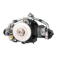
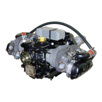
5.3.6 Ignition System
The ig ni tion sys tem con sists of:
•
2 ig ni tion coils
•
2 ig ni tion mod ules
•
1 sup port
•
4 ig ni tion leads.
The sup port, with the as sem bled coils and mod ules, is at tached to the firewall (heat con duc t ive).
If pos si ble, the in stal la tion area should be in a cool re gion, max i mum am bi ent tem per a ture 80° C.
Do not route the ig ni tion leads par al lel to the elec tri cal ca bles.
5.4 Requirements
5.4.1 L 2000 Series Engines
BILL OF MA TE RIALS FOR THE WIRING DI A GRAM
Sign De scrip tion Po si tion Part No.
B1 Sender, oil temperature attached to the engine
B2 Sender, oil pressure attached to the engine
B3 Sender, fuel quantity - selection of the designer selection of the designer
B4 (B5 -B7) Sender, CHT cylinder head 170.215.010.000
E1-E4 Spark plug attached to engine
F1 Main circuit breaker
(25A)
ETA 2-5700-K12 25A or ETA 2-5700-K12-55A
F2 Gen. circuit breaker
(20A)
ETA-2-5700-K12-20A or ETA 2-5700-K12-50A
F3-F8 Circuit breaker cockpit ETA 2-5700-K12-5A
G1 Battery 12V-28Ah (min.) firewall / airframe selection of the designer
G2 Alternator 30A or 55A attached to the engine
G4 Magneto attached to the engine
H1 Indicator light cockpit selection of the designer
 Loading...