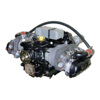
has an ex pan sion ves sel (X) to re ceive the res i due of the heated cool ant. The ex pan sion ves sel has
a pres sure cap and a vent (X
V
) to at mo sphere to pre vent ex ces sive build-up of pres sure.
A ther mo stat is not in cluded in this sys tem
1
because the tem per a ture of the air-cooled cyl in der
wall, a ma jor fac tor gov ern ing cyl in der wear, is reached very quickly. To pre vent the cyl in der
head from reach ing an op er at ing tem per a ture which may be too low, in win ter months, it is rec
-
om mended that the air frame man u fac turer in clude an aero dy namic ra di a tor blind in the de sign.
This will also re duce the sur face drag.
The crank shaft drives the cool ant pump through a pul ley-wheel/belt sys tem. A tensioning ad just
-
ment arm and jockey wheel ten sions the drive-belt.
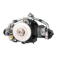
A more re cent de sign fea tures of cyl in der-cooling is the use of units made from com pos ite ma te -
ri als. This con sists of two fun nel shaped units con nected to the front of the en gine cowl ing. The
air (A
C
) flows di rectly to the cyl in ders and elim i nates the re quire ment for the air baf fles to cool
the en gine. This de sign is more ef fi cient and it is rec om mended to em body this in the de sign of
the air craft. Use a seal of 170.163.500.000 to avoid the loss of cool ing-air be tween the fun nels
and cowl ing.
Note The air frame man u fac turer might de cide to in clude a wa ter-to-oil heat exchanger in pref er e nce to
the sep a rate com po nents. They are very com pact and are used in sev eral types of automobiles.
This elim i nates the need for the cool ing ducting which is to be found in the con ven tional cool ing
sys tem. LIMBACH-Flugmotoren do not rec om mend this prac tice. The use of in di vid ual items is
rec om mended for safety. If a com po nent fails, it will not elim i nate the com plete sys tem and will
al low the air craft to re turn safely, pos si bly on re duced power.
3.1.2.1 Cylinder Cooling
The cyl in der cool ing re quires only 25% of the amount of air nec es sary for cool ing a con ven tional
air-cooled en gine in stal la tion. Pres sure cool ing is re quired for the cyl in ders.
The en gines are de liv ered with the cool ing-air ducts, for cyl in der cool ing, al ready at tached. The
cool ing air en ters two in lets and is ef fec tively di rected, by the cool ing-air ducts, to the sur face of
the cyl in der. The in ter face of the cowl ing to the cool ing-air ducts must be sealed.
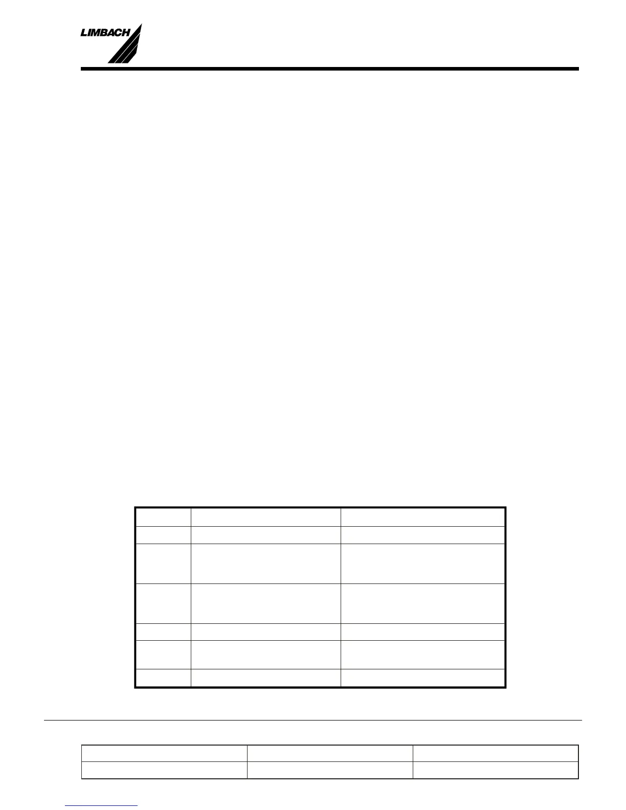
3.1.2.2 Cylinder-Head Cooling
The cyl in der-head cool ing con sists of the fol low ing com po nents (Fig.:3-2):
Pos. Item De scrip tion
Coolant pump installed on engine
C
O,R
Coolant pipes partially installed on engine
missing parts are customer
supplied items
C
O,R
Coolant hoses included in the installation kit,
missing parts are customer
supplied items
R Radiator (cooler) included in the installation kit
X Expansion vessel with pressure
cap
included in the installation kit
Thermostat optional
 Loading...