A ground ca ble from the en gine to the bat tery is re quired. It should have at least the same cross
sec tion as the starter ca ble and should be at tached to one of the starter mount ing bolts.
Warn ing: If the mag neto switch is be set to the “ON” po si tion (for ex am ple cir cuit test ing) be ware of
the “Hot-Engine”con di tion es pe cially if the pro pel ler is at tached. The bat tery must not dis
-
charge with the mag neto switch in the “ON” po si tion.
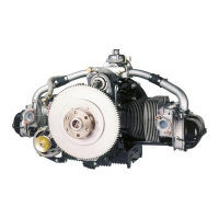
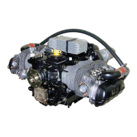
5.3 L 2400 EF Engine
5.3.1 Description
The L 2400 EF en gine has a 12V elec tri cal sys tem for the en gine electrics, the starter, the pumps
and the gen er a tor. The en gine is equipped with an elec tronic en gine man age ment sys tem that pro -
vides full con trol of the fuel and ig ni tion re quire ments of the en gine through out the com plete op -
er a tional en ve lope. Mix ture con trol, due to the am bi ent con di tions, is au to matic.
The in for ma tion re quired to cal cu late the fuel flow and ig ni tion ad vance is given in two ba sic ta
-
bles with 16 x 16 fields. This gives a to tal of 256 in di vid ual val ues for each of the two func tions.
En gine speed and throt tle an gle are used to ad dress the in for ma tion given in the ta bles. En gine re -
quire ments for op er at ing con di tions that do not ex actly cor re spond to the ta ble en tries are in ter po -
lated. Ad di tional in puts give in for ma tion on air tem per a ture, air pres sure and en gine tem per a ture.
They are used to ad just the val ues in the ba sic ta ble to the re quire ments for non-standard en vi ron
-
men tal con di tions. The En gine Con trol Unit (ECU) is the elec tronic brain.
Warn ing: Func tion of the en gine man age ment sys tem is de pend ent on the avail abil ity of elec tri cal
power.
Un like con ven tional en gines with mag ne tos, the L 2400 EF en gine will not func tion with out a
12V power source. To pro vide op er a tional be hav ior sim i lar to the con ven tional en gines that most
pi lots may be fa mil iar with, a back-up sys tem is es sen tial. This is pro vided by the emer gency
switch and the re lay box (MCU). It should en sure a sup ply of the elec tri cal power for the en gine
func tion for a min i mum pe riod of twenty min utes af ter the loss of power from the main elec tri cal
sys tem.
The emer gency switch is in cluded in the cir cuit in case the fuel pump or a sen sor cases to func
-
tion. In the emer gency op er a tional mode, the sec ond fuel pump re places the pre vi ously ac tive
pump, the sec ond speed sen sor re places the pre vi ously ac tive speed sen sor. The sen sors re v ert to
a per ma nently set re sis tance. The en gine can be started with the emer gency switch in the “Emer -
gency op er a tion“ po si tion, pro vid ing that the main switch is in the “ON“ po si tion and the main
bat tery func tions cor rectly. The hous ing has a di am e ter of 53.0 mm. The emer gency switch does
not in flu ence the elec tri cal power sup ply/pe riod of op er a tion.
The re lay box has the func tion to sup ply the en gine with elec tri cal power from the main bat t ery,
gen er a tor and the emer gency bat tery. The nom i nal cur rent is 12V. There is a 9 Amp. con sump
-
tion for en gine op er a tion. Be cause the op er a tion of the en gine is de pend ent on the func tional op -
er a tion of the elec tri cal power sup ply, the emer gency bat tery and ap pro pri ate switch ing in side the
re lay-box (MCU) is nec es sary. No elec tri cal power flows from the emer gency bat tery into the air -
craft net work but the bat tery can be con tin u ally charged. The gen er a tor pro vides the sys t em with
13.5-14.0V.
5.3.2 Connection of the Engine Electrics
5.3.2.1 Mounting of the ECU and wiring loom
The ECU should be mounted with shock mounts. For ex am ple 1 Barrymount GE 21-03-05 may
be used at the back side and 2 Flex-Loc Q-6 at the front.
 Loading...