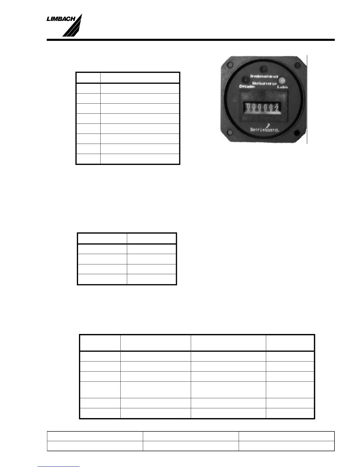
5.3.3.6 Sta tus In di ca tor
(250.215.025.000)
Pin Des ti na tion
1 X7/15 (+12 V)
2 X7/1 (Counter)
3 X7/8 (Discharge)
4 X7/7 (Charge)
5 X7/13 (GND)
6 X7/15 (+12 V)
7 Sensor, fuel pressure +
9 Sensor, fuel pressure GND
5.3.4 Fuel Pumps
The elec tri cally driven fuel pumps are con nected to the plug X9.
Drill the plugs to ac com mo date AWG 16.
Con nec tor / Pin Des ti na tion
X9 / 1 Pump 1 (+)
X9 / 3 Pump 1 (-)
X9 / 4 Pump 2 (+)
X9 / 6 Pump 2 (-)
5.3.5 Connections for the Instruments/Panel
The cock pit in stru ments are con nected to plug X7 on the ca ble loom, ECU.
Con nec tor /
Pin
Des ti na tion Com ment In stru ment P/N
X7 / 1 engine-hour counter 250.215.025.000
X7 / 6 switch (S3), then to GND engine electrics ON/OFF)
X7 / 7 yellow LED+ emergency batt. charging 250.215.025.000
X7 / 8 red LED+ emergency batt.
discharging
250.215.025.000
X7 / 10 RPM-indicator 250.215.001.000
X7 / 11 RPM-indicator 250.215.001.000
5
Prepared by: J. B. Meyer Replaces edition from: 10.03.86 Page: 5-9
Checked by: Edition: 01.03.1999 Reg. Number:
Installation Manual
L 1700, L2000 and L 2400 Series
Fig.: 5-13 Multi- Status Indicator and Hour
meter
 Loading...