10 COWLING
De sign in struc tions and ex am ples for the ducting of the air.
When de sign ing the air in lets, ducting and the air out lets, the fol low ing points must be con sid
-
ered:
• aero dy namic qual ity of the cowl ing
• func tion and ef fi ciency of the cool ing sys tem
•
sup ply of in take-air
• good ap pear ance.
10.1 L 2000 and Series
The valid edi tion of the Tech ni cal Bul le tin 44 gives use ful in struc tions for the de sign (TB 44.1).
The car bu re tor should get it´s air out of a kind of box, in which the air get´s calm.
Make sure that the out let is not blocked, e. g. by the muf fler.
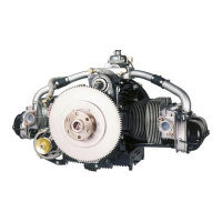
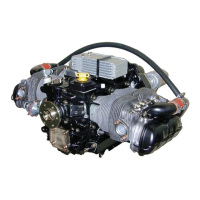
10.2 L 2400 EF Engine
10.2.0.1
Air Inlet
Air in lets are re quired for:
• cool ing air for the cyl in ders. These are con nected to the cool ing-air ducts mounted on the en -
gine. There is one each on the left and right of the spin ner (re fer to NASA re port)
•
cool ing air for the oil cooler, NACA in let, on the right side of the cowl ing
•
cool ing-air in let, a slit in the shape of a shark’s mouth for the ra di a tor, at the bot tom of the
cowl ing
•
in let for the en gine in take-air, NACA in let. An ac cu mu la tor, with an air-intake arch and an air
fil ter, is mounted on the en gine. The air fil ter sits in a con tainer.
10.2.0.2
Air Ducting
The con tainer for the air fil ter is at tached to ei ther the en gine mount or the cowl ing and should be
sealed at the cowl ing as good as pos si ble. Fresh air, at a slightly higher at mo spheric pres sure,
flows to the air-filter con tainer through the NACA in let on the left side. The pipe to the
air-pressure sen sor (in the cock pit, plug B4) is con nected to the com pos ite arched-pipe in stalled
be tween the throt tle and the air fil ter.
The air-intake arch must not be mod i fied be cause the ge om e try has an ap pre cia ble in flu ence on
the per for mance of the en gine.
The oil cooler can be housed in a con tainer at tached to the cowl ing, re tained by quick-release fas -
ten ers.
10.2.0.3
Air Outlet
 Loading...