7 EXHAUST SYSTEM
7.1 General
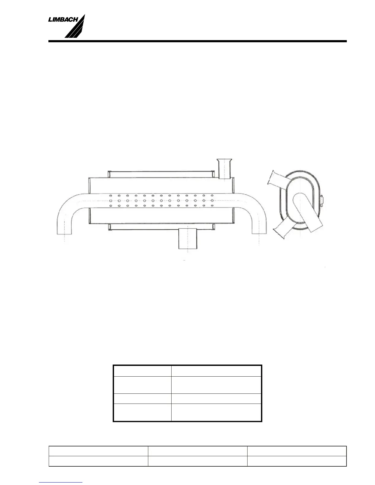
The de sign of the ex haust sys tem has a great in flu ence on the per for mance of the en gine. Be cause
of the many dif fer ent types of air craft de signs, it is not pos si ble to is sue de tailed guide lines for
the de sign of the ex haust sys tem. The ex haust pipes should be routed away from the en gine and
use the larg est bend ra dius pos si ble. All of the pipes in the ex haust sys tem should have an ex pan
-
sion joint to min i mize the ther mal stress. Flex i ble hoses or tubes are not per mit ted. Due to in -
creased re quire ments to re duce the noise lev els, a muf fler is rec om mended. The use of
ball/socket/spring con nec tions to the pipe/pot con nec tions makes the in stal la tion eas ier. Move -
ment of the en gine must be taken into ac count.
Di men sioned Draw ings are avail able from LIMBACH Flugmotoren un der the fol low ing ref er
-
ences
Dwg. No. Description
000.173.001.000 Exhaust System Design
Requirements
000.173.100.000 Silencer, Supplementary
000.173.200.000 Exhaust System Layout (Grob
G109)
Installation Manual
L 1700, L 2000 and L 2400 Series
7
Prepared by: J. B. Meyer Replaces edition from: 10.03.86 Page: 7-1
Checked by: Edition: 01.03.1999 Reg. Number:
Fig.: 7-1 Sample Exhaust System Layout L 2000 Series
 Loading...