3 COOLING
3.1 Description
3.1.1 L 2000 and Series Engines
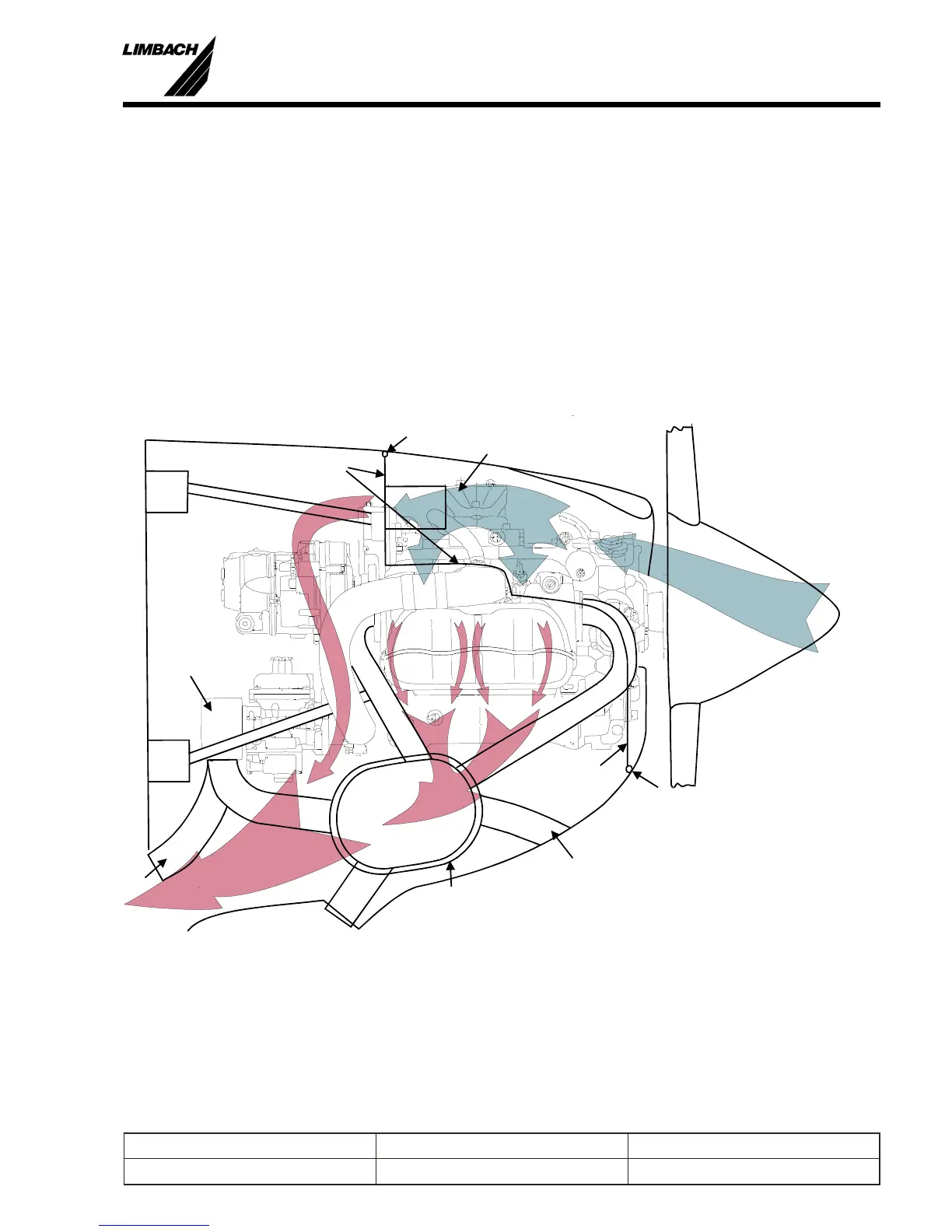
The L 1700, L 2000 and the L 2400 EB se ries en gines are air cooled. For safe op er a tion, a cowl -
ing and baf fle sys tem is re quired. The air that en ters the in lets (A) must be guided through the
finned pas sages of both the cyl in ders and the cyl in der heads. The heated air then ex its through the
cowl ing exit (E). The exit open ing should be ap prox i mately twice the size of the in let. The en
-
gine re quires air at ap prox i mately 1000 li ters/sec ond at a pres sure drop of be tween 200.0 mm and
300.0 mm of wa ter (stan dard at mo spheric pres sure). Baf fles (B) must be fit ted cor rectly to
achieve the op ti mum cool ing per for mance. The baf fles should touch the cool ing fins of the en -
gine and must be sealed (S) against the cowl ing and the engine. To ob tain the cor rect fit at the
pro pel ler is more dif fi cult but must also be achieved with care. Open ings, the size of the palm of
the hand, can be ob served in this area which re duces the cool ing per for mance.
The en gine is de signed for downdraft cool ing. Do not use up draft cool ing.
3
Prepared by: J. B. Meyer Replaces edition from: 10.03.86 Page: 3-1
Checked by: Edition: 01.03.1999 Reg. Number:
Installation Manual
L 1700, L2000 and L 2400 Series
A
E
S
S
O
B
B
C
H
M
X
Fig.: 3-1Typical Engine Installation
 Loading...