5.3.3.3 Con nec tion of RPM-Indicator with
Gen er a tor-pickup
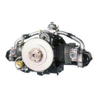
Al ter na tively an RPM-indicator with Gen er a tor-pickup
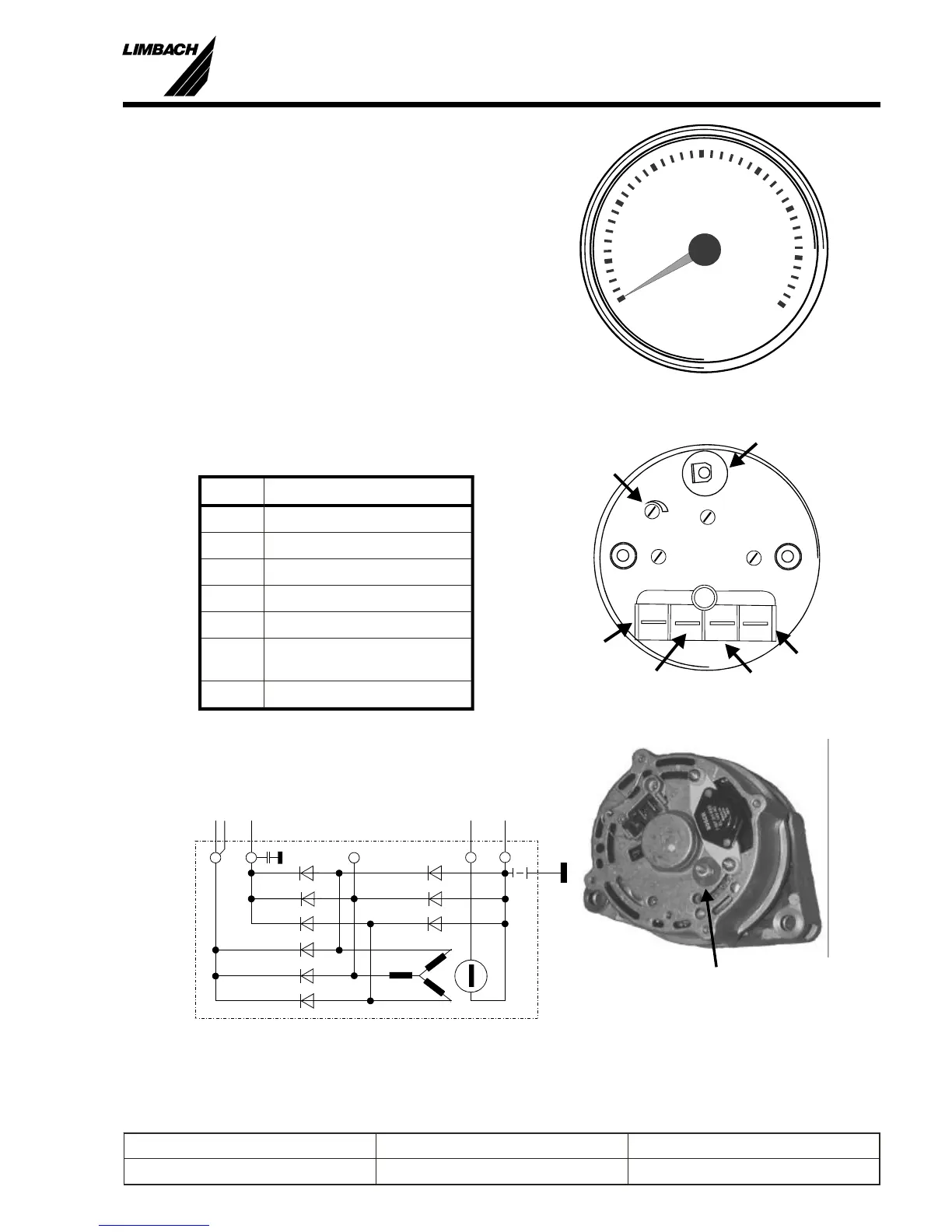
may be used (Fig.: 5-6). Check wether the Gen er a tor has
the ap pro pri ate con nec tor “W” (Fig.:5-8).
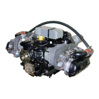
The pickup “W” on the gen er a tor is con nected with the
ap pro pri ate ter mi nal on the RPM in di ca tor (Fig.:5-7).
Note the dif fer ent con nec tors for the dif fer ent sup ply
volt ages.
Af ter in stal la tion, the in stru ment must be cal i brated.
Mea sure the pro pel ler rpm with an op ti cal ta chom e ter at
ap prox i mately 2/3 max en gine rpm and ad just the screw
“S”.
5.3.3.4 Oil pres sure and oil tem per a ture
(250.215.010.000)
Pin Des ti na tion
1 +12 V
2 +12 V (Light)
3 (GND)
4 Sensor, temperature, VDO
5 (GND)
6 Sensor, pressure 0-10 bar,
VDO
7 GND
5
Prepared by: J. B. Meyer Replaces edition from: 10.03.86 Page: 5-7
Checked by: Edition: 01.03.1999 Reg. Number:
Installation Manual
L 1700, L2000 and L 2400 Series
0
40
35
30
5
10
15
20
25
x100
rpm
Fig.: 5-6 RPM Indicator “W”
S
+
-
 Loading...