The air flow to the ra di a tor must be in de pend ent of the air flow to the cyl in ders, with care ful de
-
sign it may be pos si ble to use a com mon out let. The size of the ra di a tor is de pend ent on the aero -
dy namic con di tions such as air-speed dur ing climb, po si tion of in stal la tion and de sign of the air
in let and out let.
The rec om mended
sizes of the ra di a
-
tor are based on an
air-speed of 40 m/s
and a tem per a ture
dif fer ence of 60° C
be tween the cool
-
ant and am bi ent
air.
The size of the ra -
di a tor may be re -
duced if there is an
in crease in air ve
-
loc ity and/or cool
-
ant tem per a ture.
How ever, for
safety rea sons, a
max i mum tem per -
a ture of 110° C
must not be ex
-
ceeded.
The pipes for the cool ing wa ter have a di am e ter of 25 mm and the mix ture is 50% gly col for frost
and cor ro sion pro tec tion. There are two bleed lines from the out lets from the en gine to the ex pan -
sion ves sel. The an gle of in stal la tion of the ra di a tor is 45° and is in stalled on the brack ets of the
en gine mounts. Flex i ble hoses per mit the en gine to move in re la tion to the en gine mounts (en gine
is in stalled in rub ber anti-vibration blocks). Make sure that the out let for the cool ing air is of an
ad e quate size . In stall the ex pan sion ves sel at the high est point (for bleed ing).
3.1.2.3 Oil Cooling
Oil cool ing (Fig.: 3-3) re quires an other ra di a tor or heat exchanger, which can be slightly larger
than re quired be cause of the ther mo stat. The oil cooler is de liv ered within the in stal la tion kit.
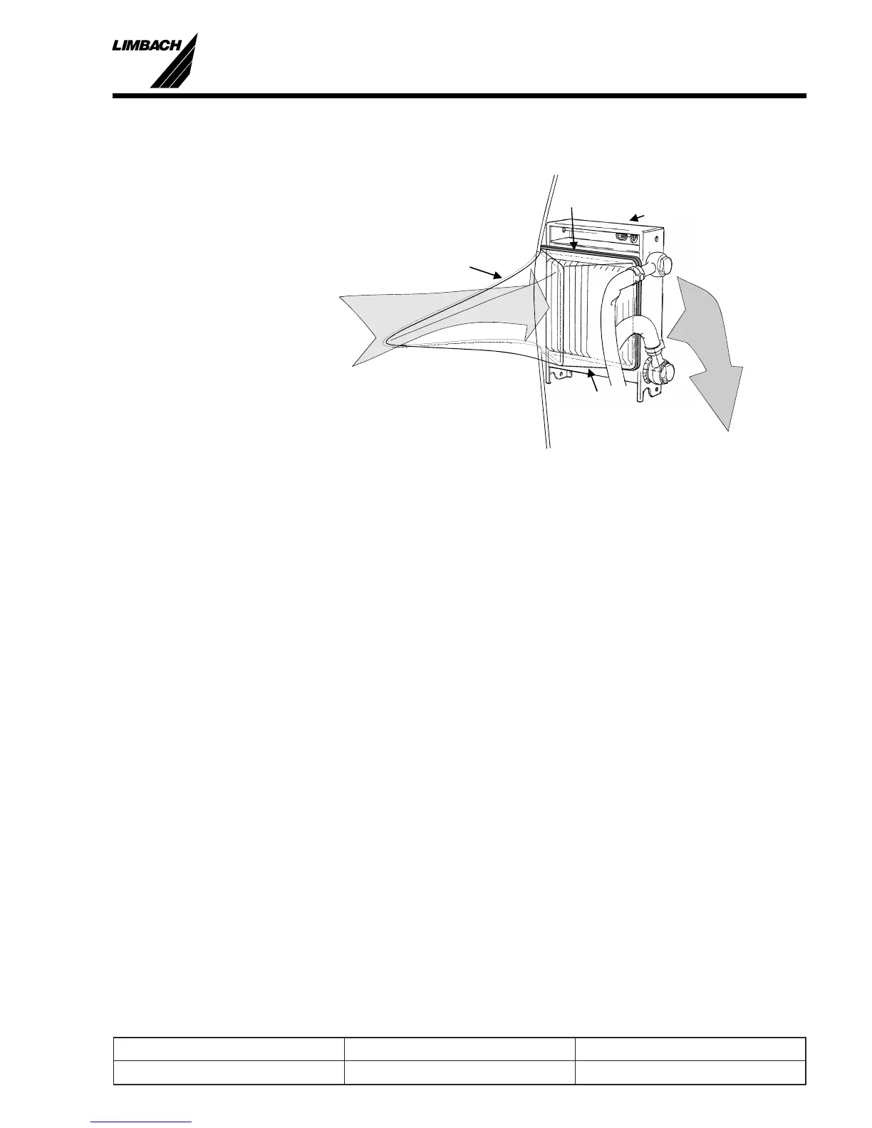
The oil cooler may be at tached di rectly to the cowl ing and the cool ing air is pro vided through an
NACA in let (N) and a Duct (D) to the oil cooler (O). The cooler must be sealed against the duct
with an elas tic seal (S) to pre vent an air bleed to the in side of the en gine cowl ing. The air bleed
would cause a dis tur bance of the pres sure dif fer en tial which is used to op er ate the air-based por -
tion of the cool ing sys tem. The warm air ex it ing from the cooler must pass through the main
cool ing air exit. Be sure to di men sion it ac cord ingly.
Note: The duct (D) must also be sealed to wards the cowl ing. Keep in mind that the in stal la tion sit u a -
tion may change with man u fac tur ing tol er ances which may be very large with all de pend en cies
con sid ered. Also con sider that the enduser may not al ways fit the cowl ing cor rectly and that the
seal ing should func tion in such cases also. In spec tion of the seals should be in cluded as an item
in your maintanance doc u men ta tion.
3
Prepared by: J. B. Meyer Replaces edition from: 10.03.86 Page: 3-5
Checked by: Edition: 01.03.1999 Reg. Number:
Installation Manual
L 1700, L2000 and L 2400 Series
D
O
S
In
Out
N
Fig.:3-3 Oil Cooler Installation L 2400 EF (Sample)
 Loading...