Page 58 of 192
Mechanical spline:
The splines function so that the actuator can only push, not pull. During pull in the actuator, the inner tube is lifted off the thread bush, and the
actuator can therefore never pull a load, only push. See figure 8.
Functional test of mechanical splines:
When the piston rod is at the innermost position, it must be possible to pull it out manually to its full travel length and to press it in again without
much resistance and without using the motor. If this is not possible, contact your nearest LINAK dealer.
Electrical splines:
In the rear fixture on the actuator, a microswitch is fitted, which turns off the motor, if the actuator is exposed to pull forces.
Functional test of electrical splines
When the actuator is correctly fixed/mounted, the inward movement of the piston must stop, when the actuator is pulled or the movement is blocked,
so that the back fixture is not put under undue stress/tension. For mounting, see Figure 7.
Quick release
When the quick release arm, see Figure 9, is turned counter clockwise approx. 75° and fixed here, the piston rod is released and can now be
pressed in to its innermost position or pulled out to its outermost position. When the quick release arm is released, the arm turns back and the
actuator functions normally again. The cable must not be tight.
Warning
• If the actuator does not work as described above, the risk of injury due to squeezing can arise. Therefore, the actuator must immediately be sent
for service at the nearest, authorised LINAK workshop.
• The actuator must not be used in pull applications when the quick release is activated, as the risk of personal injury can arise.
• Do only use the actuator within specified working limits.
Options:
• Mechanical spline: When using the actuator in a vertical position, the force needed to activate the mechanical spline is maximum 60 N + the
weight of the application. To reengage the spline function, a force of maximum 60N is needed. Same installation dim. as standard actuator.
• A modified Bowden cable holder is available (as a special article), with better cable alignment and improved guidance of the cables.
• Electric spline: When using the actuator in a vertical position, the force needed to activate the electric spline is maximum 100 N + the weight
of the application. To reengage the spline function, a force of maximum 100 N is needed.
Usage:
• Duty cycle: 2/18 – 2 minutes continuous use followed by 18 minutes not in use
• Ambient temperature: + 5 °C to + 40 °C
• Compatibility: CB9 with EAS, CB12 with EAS, CB14*, CB18, CB20 and CBJ, CB6 OBL/ F, CB16 OBL/ F,
(* = only possible with customized software)
• Approvals: IEC60601-1, ANSI / AAMI ES60601-1 and CAN / CSA-22.2 No 60601-1 for LA34 24V zinc and composite versions.
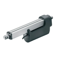
LA34 is a technological state-of-the-art actuator that, due to its innovative construction
can push up to 10000 N at a speed of 5 mm/sec. and with a current consumption of
approx. 7 Amp. The strong LA34 actuator is made in a low weight composite material.
Its compact design, the outstanding performance and a wide range of safety options
makes LA34 the right choice for a variety of medical and industrial applications.
The LA34 24V actuator is approved according to IEC 60601-1, ANSI / AAMI ES60601-1,
and CAN / CSA-22.2 No 60601-1.
Reed-switch:
The Reed-switch gives a number of pulses for each rotation of the motor. These pulses
are used to calculate the piston rod’s position as well as to control several actuators
running in parallel.
Your nearest LINAK dealer can inform the number of pulses per stroke length.
Regarding Reed-switch connection, see Figure 6.10.
Recommendations
• Power supply without current cut-off can cause serious damage to the actuator if mechanical stop is encountered or the actuator movement is
blocked in another way.
• LINAK control boxes are designed so that they will short-circuit the motor terminals (poles) of the actuator(s) when the actuator(s) are not running.
This solution gives the actuator(s) a higher self-locking ability. If the actuator(s) are not connected to a LINAK control box the terminals of the
motor must be short-circuited to achieve the self-locking ability of the actuator.
13. LA34 (MEDLINE
®
CARELINE
®
)